


www.nexusrobot.com Robot Kits manual
26
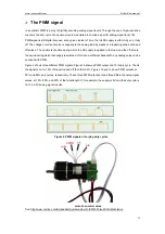
¾
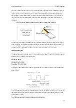
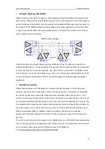
Network topology with RS485
RS485 is the only of the interfaces capable of internetworking multiple transmitters and receivers in the
same network. When using the default RS485 receivers with an input resistance of 12 k
Ω
it is possible to
connect 32 devices to the network. Currently available high-resistance RS485 inputs allow this number to
be expanded to 256. RS485 repeaters are also available which make it possible to increase the number
of nodes to several thousands, spanning multiple kilometers. And that with an interface which does not
require intelligent network hardware
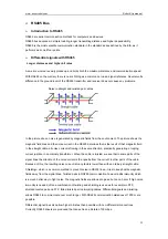
RS485 network topology
In the picture above, the general network topology of RS485 is shown. N nodes are connected in a
multipoint RS485 network. For higher speeds and longer lines, the termination resistances are necessary
on both ends of the line to eliminate reflections. Use 100
Ω
resistors on both ends. The RS485 network
must be designed as one line with multiple drops, not as a star. Although total cable length maybe shorter
in a star configuration, adequate termination is not possible anymore and signal quality may degrade
significantly.
¾
RS485 functionality
Default, all the senders on the RS485 bus are in tri-state with high impedance. In most higher level
protocols, one of the nodes is defined as a master which sends queries or commands over the RS485
bus. All other nodes receive these data. Depending of the information in the sent data, zero or more
nodes on the line respond to the master. In this situation, bandwidth can be used for almost 100%. There
are other implementations of RS485 networks where every node can start a data session on its own. This
is comparable with the way ethernet networks function. Because there is a chance of data collosion with
this implementation, theory tells us that in this case only 37% of the bandwidth will be effectively used.
With such an implementation of a RS485 network it is necessary that there is error detection
implemented in the higher level protocol to detect the data corruption and resend the information at a
later time.
There is no need for the senders to explicity turn the RS485 driver on or off. RS485 drivers automatically
return to their high impedance tri-state within a few microseconds after the data has been sent. Therefore
it is not needed to have delays between the data packets on the RS485 bus.
See: http://www.lammertbies.nl/comm/info/RS-485.html#intr
Содержание Nexus Robot
Страница 74: ...www nexusrobot com Robot Kits manual 70 Sample Wiring Diagram for RB004 2WD V2 0...
Страница 92: ...www nexusrobot com Robot Kits manual 88 Diagram for Omni3WD_V1 0...
Страница 96: ...www nexusrobot com Robot Kits manual 92 Diagram_Omni3WD_V3 3...
Страница 118: ...www nexusrobot com Robot Kits manual 114 Sample Wiring Diagram for RB011 Mecanum 4WD V4 1...