www.nexusrobot.com Robot Kits manual
20
you need to drive more than one or two, you'll probably need to power them from a separate supply (i.e.
not the +5V pin on your Arduino). Be sure to connect the grounds of the Arduino and external power
supply together. As mentioned earlier, most servos expect a pulse width between 1-2 ms, however, a
range of 0.5 ms to 2.5 ms (500-2500
μ
s) may be required, depending on your servo. Experiment as
necessary.
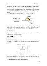
Hi-Tec Servo Motors have three wires coming out of them.
·Red - Power (4.8v-6v)
·Black (Ground)
·Yellow (Signal)
The power & ground wires are hooked directly up to whatever battery or power supply you are using to
power the servos. The Signal wire will be hooked up to the microcontroller used to control the servo, in
our case the PIC. A noticeable first impression, the servo only requires 1 pin from the pic.
The PWM Signal
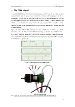
The signal that we need to create inorder to control the servos is called a Pulse With Modulation signal or
PWM for short. The general requirements are:
Frequency: 50Hz
Up-time: 0.9mS->2.1mS
Down-time: 19.1mS-17.9mS
At first glance these definitions & numbers might make little or no sense. So lets look at a simple PWM
wave at 50Hz.
So a PWM wave is just a signal that changes between 0 volts & 5 volts (digital logic 0 and 1). We see that
the wave is symmetrical; uptime is 10mS & downtime is 10mS which when added together give us the
period (10mS + 10mS )
See: http://www.pyroelectro.com/tutorials/servo_motor/index.html
Содержание Nexus Robot
Страница 74: ...www nexusrobot com Robot Kits manual 70 Sample Wiring Diagram for RB004 2WD V2 0...
Страница 92: ...www nexusrobot com Robot Kits manual 88 Diagram for Omni3WD_V1 0...
Страница 96: ...www nexusrobot com Robot Kits manual 92 Diagram_Omni3WD_V3 3...
Страница 118: ...www nexusrobot com Robot Kits manual 114 Sample Wiring Diagram for RB011 Mecanum 4WD V4 1...


