background image

Page 8

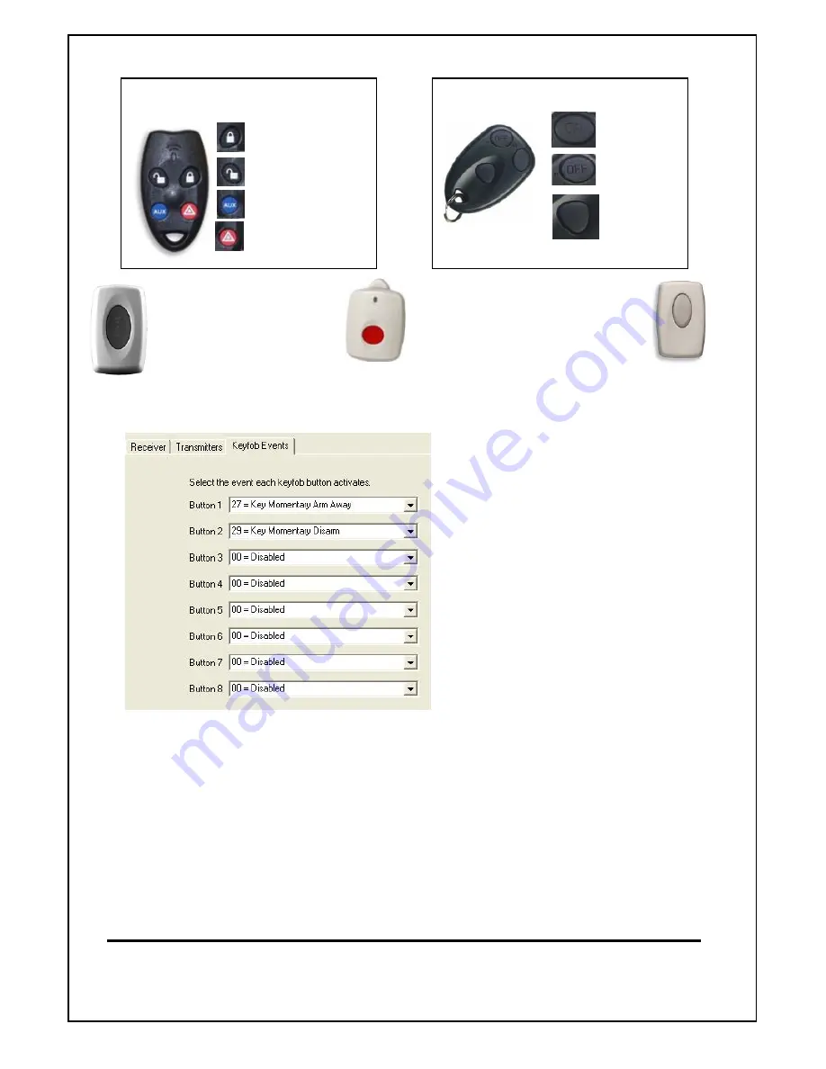
Programming Buttons on Radio Keys.

RK4 Radio Keys (Keyfobs)

Button 1

Button 2

Button 3

Button 4

RK3 Radio Keys (Keyfobs)

Button 1

Button 2

Button 8

Recommended for M1 Systems

As Default buttons 1 & 2 are programmed as Arm & Disarm. Buttons 3, 4 & 8 can be

programmed as required. This can be done either via the Keyfob events or in the Rules.

Changing the function of the Keyfob
buttons in the "Keyfob Events" screen
will change the function of these buttons
on ALL programmed Keyfobs.

It is also possible to have each button
on each individual Keyfob perform
different functions to the same button
on other keyfobs. (e.g. Aux (button 3)
on keyfob 1 may open a garage door,
where Aux button on keyfob 2 may turn
lights on or off.

If this is required then select "Disabled"
in the Keyfob Events screen and use
rules as detailed below to set buttons
on each keyfob.

Ness Security Products Pty Ltd

Sydney (02) 8825 9222 - Melbourne (03) 9875 6400 - Brisbane (07) 3399 4910 - Perth (08) 9328 2511 - Adelaide (08) 8152 0000

email [email protected]

Ness Document No. 895-364

Programming Individual Buttons on Radio Keys each key.

Using "rules" programming within the M1 each button on each radio key can be programmed
individually as the following examples show.
To use this feature, ensure the buttons in the Keyfob Events, in the wireless section are disabled for
the individual buttons to be used. The following "rules" will then enable them.
EXAMPLE:
             Whenever RF KEYFOB BUTTON 3 is


ACTIVATED

                     AND Last User was Greg Kingsley (user 2)
                            THEN Turn Garage Door1 (Out 9) ON for 2 seconds

              Whenever RF KEYFOB BUTTON 3 is


ACTIVATED

                     AND Last User was Pam Kingsley (user 3)
                             THEN Turn Garage Door2 (Out 10) ON for 2 seconds

The Emergency panic button
& Medical (Mobile) pendant
is learnt in as button 8

The Wireless Doorbell button
is learnt in as button 4

Содержание M1RF

Страница 1: ...Page 1 INSTALLATION MANUAL Ness M1RF Wireless Receiver Specifications Installation and Programming Ness Document No 895 364 Version 1 4 May 2008 ...

Страница 2: ...the 4 Wire Data Bus DIP Switch Address Settings Flash Memory for Firmware Updating Status and Diagnostic LED On Board EOL Bus Termination Jumper Supplied in easy to mount equipment housing The Ness M1RF receiver is compatible with the following Wireless transmission devices at initial release Ness R15 PIR 100 663 Ness R15 PET 100 663PET Ness R12 PIR 100 691 Ness RR1 Radio Reed 100 662 Ness RR2 Uni...

Страница 3: ...nes A B and provides a clean organized management of the data bus wires Data Bus E O L Termination is Very Important INSTALLATION AND ENROLLMENT OF NESS M1RF RECEIVER Select a suitable location for the receiver not within a metal cabinet with an ambient temperature range between 0 and 49 C 32 to 120 F The Ness M1RF Receiver connects onto the M1 data bus which uses 4 wires However CAT5 or CAT6 eigh...

Страница 4: ...er module for the zone to be allocated for wireless Note You can add assign more than 16 zones of wireless on one wireless receiver by adding more wireless expanders and allocating more groups to wireless If the group is greyed out then those zones will already exist in this account Once zones have been allocated as Wireless Zones the Input module will be shown as a Wireless rather than a Input Ex...

Страница 5: ... M1 voice is enabled not available on M1 EZ8 systems the system will provide voice prompts and feedback of enrolment If the voice prompt speaks Press Transmitter button for If the zone prompt does not speak a Voice description then it is will be because you have not entered one in for the Zone beingenroled Once enrolled the system will automatically move to learn mode of the next zone If a zone ha...

Страница 6: ...tters have been learnt into the M1 their data can be uploaded to NessRP RIGHT mouse click on Wireless Setup and then select Receive Wireless Setup Once data has been received their Tx ID s can be viewed when wireless Transmitters tab is selected ...

Страница 7: ...the radio key to be set to This can be User 1 255 excluding 200 203 as these are reserved Tx ID or DL This is the Radio Transmitters unique ID If this ID is known e g learnt in and recorded from another test system it can be manually entered and downloaded into the M1 which will allow the transmitter to work To change setting in the transmitter settings click on the Zone and then change Deleting T...

Страница 8: ...etailed below to set buttons on each keyfob Ness Security Products Pty Ltd Sydney 02 8825 9222 Melbourne 03 9875 6400 Brisbane 07 3399 4910 Perth 08 9328 2511 Adelaide 08 8152 0000 email m1support ness com au Ness Document No 895 364 Programming Individual Buttons on Radio Keys each key Using rules programming within the M1 each button on each radio key can be programmed individually as the follow...

Отзывы: