background image

POC-300 Series 

67 

3.6 

Wall Mount Bracket Installation (with WM-300H) 

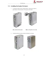
1. 

To install the full size wall mount bracket, locate a flat surface area (wall, ceiling, 

etc.) free from obstructions that meets the following dimensions. 


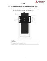
NOTE 

All measurements are in millimeters (mm).


Содержание POC-300

Страница 1: ...Neousys Technology Inc POC 300 Series User Manual Revision 1 0 ...

Страница 2: ... 2 0 Port 28 2 2 2 Power Button 29 2 2 3 Reset Button 30 2 2 4 Gigabit Ethernet 31 2 2 5 System Status LED 32 2 2 6 DVI I Port 33 2 2 7 USB 3 0 Port 34 2 2 8 IEEE 802 3at Power over Ethernet Port 1 2 POC 300 POC 320 Only 35 2 2 9 3 Pin Terminal Block for DC Input Ignition Input 36 2 3 POC 300 Series Top Panel 37 2 3 1 COM Port COM1 38 2 3 2 COM Ports COM2 COM3 COM4 39 2 3 3 3 5mm Microphone in Spe...

Страница 3: ... Modes of Ignition Power Control 80 4 BIOS Settings 4 1 COM1 Port Configuration 83 4 2 COM2 3 4 Port Configuration 84 4 3 SATA Interface Speed 85 4 4 C States 86 4 5 Wake on LAN 87 4 6 Power On after Power Failure 88 4 7 Position New Boot Device 89 4 8 Watchdog Timer 90 4 9 Select a Boot Device 91 5 OS Support and Driver Installation 5 1 Operating System Compatibility 92 5 2 Driver Installation 93...

Страница 4: ...Table of Contents 4 StopDICOS 108 DI COS Example 108 ...

Страница 5: ... in advance with Neousys Technology Inc Customer is solely responsible for ensuring the compatibility and interoperability of the third party s products Customer is further solely responsible for ensuring its systems software and data are adequately backed up as a precaution against possible failures alternation or loss For questions in regards to hardware software compatibility customers should c...

Страница 6: ...to part 15 of the FCC Rules These limits are designed to provide reasonable protection against harmful interference when the equipment is operated in a commercial environment This equipment generates uses and can radiate radio frequency energy and if not installed and used in accordance with the instruction manual may cause harmful interference to radio communications Operation of this equipment i...

Страница 7: ...represent commitment from Neousys Technology Inc Neousys Technology Inc shall not be liable for any direct indirect special incidental or consequential damages arising from the use of the product or documentation nor for any infringement on third party rights Patents and Trademarks Neousys the Neousys logo Expansion Cassette MezIO TM are registered patents and trademarks of Neousys Technology Inc ...

Страница 8: ...r cords and other connection cables away from foot traffic Do not place items over power cords and make sure they do not rest against data cables Shutdown disconnect all cables from the system and ground yourself before touching internal modules Ensure that the correct power range is being used before powering the device Should a module fail arrange for a replacement as soon as possible to minimiz...

Страница 9: ...ly as possible while assuring proper connector engagement ESD Precautions Handle add on module motherboard by their retention screws or the module s frame heat sink Avoid touching the PCB circuit board or add on module connector pins Use a grounded wrist strap and an anti static work pad to discharge static electricity when installing or maintaining the system Avoid dust debris carpets plastic vin...

Страница 10: ...bout This Manual About This Manual This manual introduces and demonstrates installation procedures of Neousys POC 300 series systems Revision History Version Date Description 1 0 Nov 2017 Initial release ...

Страница 11: ...GPU performance over previous E3800 series platform For applications such as industrial automation machine vision and real time surveillance can all benefit from its higher throughput performance Neousys POC 300 series provides rich I O ports it has one Gigabit Ethernet port two 802 3at Gigabit PoE ports two USB3 0 ports two USB2 0 ports one DVI I connector for VGA DVI dual video output four COM p...

Страница 12: ...ammable RS 232 422 485 port COM1 3x 3 wire RS 232 ports COM2 3 4 or 1x RS 422 485 port COM2 USB 2x USB 3 0 ports 2x USB 2 0 ports Audio 1x speaker out 1x microphone in Internal I O Interface Mini PCIe 1x full size mini PCI Express slot with USIM socket Storage Interface mSATA 1x half size mSATA port Power Supply DC Input Built in 8 35 VDC DC input Input Connector 3 pin pluggable terminal block for...

Страница 13: ...s Half sine 11 ms Duration w SSD according to IEC60068 2 27 EMC CE FCC Class A according to EN 55022 EN 55024 The 100 CPU GPU loading for high temperature test is applied using Passmark BurnInTest v8 0 For detail testing criteria please contact Neousys Technology For sub zero operating temperature a wide temperature HDD drive or Solid State Disk SSD is required ...

Страница 14: ... 4 or 1x RS 422 485 port COM2 USB 2x USB 3 0 ports 2x USB 2 0 ports Audio 1x speaker out 1x microphone in Internal I O Interface Mini PCIe 1x full size mini PCI Express slot with USIM socket Storage Interface mSATA 1x half size mSATA port Power Supply DC Input Built in 8 35 VDC DC input Input Connector 3 pin pluggable terminal block for DC input Max Power consumption 19 68W 0 82A 24V Mechanical Di...

Страница 15: ...ms Duration w SSD according to IEC60068 2 27 EMC CE FCC Class A according to EN 55022 EN 55024 The 100 CPU GPU loading for high temperature test is applied using Passmark BurnInTest v8 0 For detail testing criteria please contact Neousys Technology For sub zero operating temperature a wide temperature HDD drive or Solid State Disk SSD is required ...

Страница 16: ...grammable RS 232 422 485 port COM1 3x 3 wire RS 232 ports COM2 3 4 or 1x RS 422 485 port COM2 USB 2x USB 3 0 ports 2x USB 2 0 ports Audio 1x speaker out 1x microphone in Internal I O Interface Mini PCIe 1x full size mini PCI Express slot with USIM socket Storage Interface mSATA 1x half size mSATA port Power Supply DC Input Built in 8 35 VDC DC input Input Connector 3 pin pluggable terminal block f...

Страница 17: ...s Half sine 11 ms Duration w SSD according to IEC60068 2 27 EMC CE FCC Class A according to EN 55022 EN 55024 The 100 CPU GPU loading for high temperature test is applied using Passmark BurnInTest v8 0 For detail testing criteria please contact Neousys Technology For sub zero operating temperature a wide temperature HDD drive or Solid State Disk SSD is required ...

Страница 18: ... 3x 3 wire RS 232 ports COM2 3 4 or 1x RS 422 485 port COM2 USB 2x USB 3 0 ports 2x USB 2 0 ports Audio 1x speaker out 1x microphone in Internal I O Interface Mini PCIe 1x full size mini PCI Express slot with USIM socket Storage Interface mSATA 1x half size mSATA port Power Supply DC Input Built in 8 35 VDC DC input Input Connector 3 pin pluggable terminal block for DC input Max Power consumption ...

Страница 19: ...ms Duration w SSD according to IEC60068 2 27 EMC CE FCC Class A according to EN 55022 EN 55024 The 100 CPU GPU loading for high temperature test is applied using Passmark BurnInTest v8 0 For detail testing criteria please contact Neousys Technology For sub zero operating temperature a wide temperature HDD drive or Solid State Disk SSD is required ...

Страница 20: ...POC 300 Series 20 1 5 Dimension 1 5 1 Superior View NOTE All measurements are in millimeters mm ...

Страница 21: ...POC 300 Series 21 1 5 2 Front Panel View NOTE All measurements are in millimeters mm ...

Страница 22: ...POC 300 Series 22 1 5 3 Bottom View NOTE All measurements are in millimeters mm ...

Страница 23: ...es with various mounting options such as DIN rail and wall mount bracket DIN rail mount clip is shipped with POC 300 series as standard mounting option Two optional mounting brackets WM 300V and WM 300H are available for wall mount applications 1 6 1 DIN Rail Mount Clip ...

Страница 24: ...POC 300 Series 24 1 6 2 Wall Mount Bracket WM 300V NOTE All measurements are in millimeters mm ...

Страница 25: ...POC 300 Series 25 1 6 3 Wall Mount Bracket WM 300H NOTE All measurements are in millimeters mm ...

Страница 26: ...missing or damaged please contact your local dealer or Neousys Technology 2 1 Unpacking the System Item Description Qty 1 POC 300 310 320 330 ultra compact fanless controller Please verify additionally purchased accessories such as DDR3L module or mSATA SSD etc 1 2 DVI to VGA adapter 1 3 3 pin pluggable terminal block 1 4 Neousys Drivers Utilities DVD 1 5 DIN Rail Mount Clip 1 6 Screw package 1 ...

Страница 27: ...Gigabit Ethernet ports offer fast network access 5 System status LED Four system LEDs Ignition control IGN Watchdog Timer WDT Hard Disk Drive HDD and Power PWR 6 DVI I port DVI I offers both DVI and VGA signals You can use the DVI to VGA adapter to connect a VGA display or use Y cable to have DVI VGA dual display output They support resolutions up to 1920 x 1200 7 USB 3 0 port USB 3 0 port up to 5...

Страница 28: ...roller in Atom E3950 Pentium N4200 SoC and are backward compatible with USB 1 1 and USB 1 0 devices Legacy USB support is also provided so you can use USB keyboard mouse in DOS environment xHCI driver is supported natively in Windows 10 therefore you do not need to install xHCI driver to utilize USB functions on POC 300 series ...

Страница 29: ...p green To turn off the system issuing a shutdown command in OS is preferred or you can simply press the power button To force shutdown when the system freezes press and hold the power button for 5 seconds Please note that there is a 5 second interval between on off operations i e once turning off the system there is a 5 second wait before you can power on the system and vice versa ...

Страница 30: ...reset button is used to manually reset the system in case of system halt or malfunction To avoid unexpected reset the button is purposely placed behind the panel To reset please use a pin like object eg tip of a pen to access the reset button ...

Страница 31: ...thernet cable the LEDs on the RJ45 connector indicate connection status and speed Active Link LED Right LED Color Status Description Yellow Off Ethernet port is disconnected On Ethernet port is connected and no data transmission Flashing Ethernet port is connected and data is transmitting receiving Speed LED Left LED Color Status Description Green or Orange Off 10 Mbps Green 100 Mbps Orange 1000 M...

Страница 32: ...e following table Indicator Color Description PWR Green Power indicator lid when system is on HDD Red Hard drive indicator flashing when SATA HDD is active WDT Yellow Watchdog timer indicator flashing when watchdog timer has started IGN Green If ignition option MezIO V20 is applied this LED is used to indicate ignition signal status lid when IGN signal is applied ...

Страница 33: ...HD graphics engine and support up to 1920 x 1200 resolution For VGA monitor Neousys offers a specialized DVI to VGA adapter as an accessory shipped with the system This adapter supports VGA DDC signals and thus eliminates compatibility issues with VGA monitors Or you can use a DVI I to VGA DVI D Y cable to support two independent display outputs DVI to VGA adapter Optional DVI to VGA DVI Y cable ...

Страница 34: ...roller Interface controller in Atom E3950 Pentium N4200 SoC and are backward compatible with USB 2 0 USB 1 1 and USB 1 0 devices Legacy USB support is also provided so you can use USB keyboard mouse in DOS environment xHCI driver is supported natively in Windows 10 therefore you do not need to install xHCI driver in prior to utilize USB function on POC 300 series ...

Страница 35: ...Device PD PoE automatically detects and determine if the connected device is PoE PD or not before supplying power making it compatible with standard Ethernet devices as well Active Link LED Right LED Color Status Description Yellow Off Ethernet port is disconnected On Ethernet port is connected and no data transmission Flashing Ethernet port is connected and data is transmitting receiving Speed LE...

Страница 36: ...rovided The screw clamping mechanism on the terminal block offers connection reliability when wiring DC power In addition to DC power input this terminal block can also accept ignition signal input IGN when ignition control module eg MezIO V20 is installed for in vehicle applications WARNING Please make sure the voltage of DC power is correct before you connect it to the system Supplying a voltage...

Страница 37: ...hip and antenna holes for antenna installation No Item Description 1 COM port 1 Software programmable RS 232 422 485 port 2 COM port 2 3 4 Can be configured as COM2 single RS 422 485 port COM2 COM3 COM4 three 3 wire RS 232 ports 3 Microphone in 3 5mm microphone in jack for voice input 4 Speaker out 3 5mm speaker out microphone out jack for sound output 5 Opening reserved for SMA antenna installati...

Страница 38: ...ble RS 232 422 485 port via 9 pin D Sub male connector The operation mode slew rate and termination of COM1 can be set in BIOS setup utility The following table describes the pin definition of COM ports COM1 Pin RS 232 Mode RS 422 Mode RS 485 Mode Two wire 485 1 DCD 2 RX 422 TXD 485 TXD RXD 3 TX 422 RXD 4 DTR 422 RXD 5 GND GND GND 6 DSR 7 RTS 8 CTS 422 TXD 485 TXD RXD 9 RI ...

Страница 39: ... 3 wire RS 232 ports COM2 COM3 COM4 Please refer to COM2 3 4 Port Configuration for configuring operation mode An optional 1 to 3 Y cable is available to connect three RS 232 devices COM2 3 4 Pin 1 to 3 Y cable The following table describes the pin definition of the COM port 3 port RS 232 COM2 3 4 Single port RS 422 485 Pin COM2 COM3 COM4 Pin RS 422 RS 485 1 1 2 RX 2 TxD TxD RxD 3 TX 3 RxD 4 TX 4 ...

Страница 40: ...50 Pentium N4200 SoC and Realtek ALC262 codec There are two audio jacks on the top panel The port is used for microphone input and port is used for speaker output To utilize the audio function in Windows you need to install corresponding drivers for both Intel HD audio and Realtek ALC262 codec Please refer to the section Driver Installation ...

Страница 41: ...ae Opening The system offers two SMA antenna openings reserved for SMA antenna installations Users can take advantage of these two openings when installing mini PCIe module for wireless communication reception such as 3G 4G GPS or WiFi ...

Страница 42: ...mini PCIe slot with USIM slot a half size mSATA port and a MezIO TM port for application oriented expansion purposes 2 4 1 DDR3L SO DIMM Socket The system has an internal SO DIMM slot supporting DDR3L 1866 memory module up to 8GB in capacity The L in DDR3 L 1866 denotes Low Voltage 1 35V type SO DIMM memory modules ...

Страница 43: ...ini PCIe socket is designed with SIM card support With a SIM card installed your system can access the internet via your network provider s 3G 4G network For wireless WIFI 3G 4G communication there are two SMA antenna openings at the top of the system NOTE When MezIO D230 230 module is installed the mini PCIe socket is not available due to mechanical interference ...

Страница 44: ...5 PERp0 26 GND 27 GND 28 1 5V 29 GND 30 SMB_CLK 31 PETn0 32 SMB_DATA 33 PETp0 34 GND 35 GND 36 USB_D 37 GND 38 USB_D 39 3 3Vaux 40 GND 41 3 3Vaux 42 LED_WWAN 43 GND 44 LED_WLAN 45 Reserved 46 LED_WPAN 47 Reserved 48 1 5V 49 Reserved 50 GND 51 Reserved 52 3 3Vaux WARNING Some off the shelf mini PCIe 4G modules use 1 8V I O signals instead of 3 3V I O and may cause signal interference Installing an ...

Страница 45: ...f size mSATA socket You can install a half size mSATA SSD for operating system installation The half size mSATA SSD has all the advantages of solid state disk technology such as lower power consumption and is higher shock vibration resistant over traditional hard disk drives ...

Страница 46: ... 6 1 5V 7 8 9 GND 10 11 12 13 14 15 GND 16 Mechanical Key 17 18 GND 19 20 21 GND 22 23 SATA_Rxp 24 3 3Vaux 25 SATA_Rxn 26 GND 27 GND 28 1 5V 29 GND 30 SMB_CLK 31 SATA_Txn 32 SMB_DATA 33 SATA_Txp 34 GND 35 GND 36 37 GND 38 39 3 3Vaux 40 GND 41 3 3Vaux 42 43 44 45 46 47 48 1 5V 49 50 GND 51 52 3 3Vaux ...

Страница 47: ...also mechanically reliable benefited from its 3 point mounted mezzanine structure A MezIO TM module can leverage these signals to implement comprehensive I O functions POC 300 series incorporates MezIO TM interface and universal mechanical design to accommodate Neousys standard MezIO TM modules For customers who want to develop their own MezIO TM module Neousys provides MezIO TM design documents o...

Страница 48: ... Reserved Reserved 13 14 CLK100_N_0 PCIe clock pair Ground GND 15 16 GND Ground Reserved UID_LED 17 18 PCIE_TXP_1 PCIe data pair Platform reset signal PLT_RST 19 20 PCIE_TXN_1 PCIe data pair USB data pair USBP5_N 21 22 PCIE_RXP_1 PCIe data pair USB data pair USBP5_P 23 24 PCIE_RXN_1 PCIe data pair Ground GND 25 26 GND Ground SMB bus SMB_DATA 27 28 CLK100_P_1 PCIe clock pair SMB bus SMB_CLK 29 30 C...

Страница 49: ...ition power control Model Description Product Photo MezIO R11 SATA port MezIO R12 SATA port 4x isolated DI 4x isolated DO MezIO C180 50 4 port RS 232 422 485 4 port RS 232 MezIO C181 50 4 port RS 232 422 485 4 port RS 422 485 MezIO D220 50 8 CH isolated DI 8 CH isolated DO MezIO D230 50 16 CH isolated DI 16 CH isolated DO MezIO V20 16 mode ignition power control When a MezIO D230 or MezIO D220 mod...

Страница 50: ... and service this product to avoid injury or damage to the system Please observe all ESD procedures at all times to avoid damaging the equipment Before disassembling your system please make sure the system has powered off all cables and antennae power video data etc are disconnected Place the system on a flat and sturdy surface remove from mounts or out of server cabinets before proceeding with th...

Страница 51: ...d or MezIO TM module you need to disassemble the POC 300 system enclosure 1 To disassemble POC 300 unfasten the three 3 screws shown in the illustration A and the two 2 screws shown in illustration B below Illustration A Illustration B 2 Gently slide the L shaped enclosure open to gain access to internal I O connectors ...

Страница 52: ...0 series motherboard Please follow the procedures below to install the memory module 1 Disassemble the system enclosure 2 The SO DIMM slot can be located once the enclosure has been removed 3 To install insert the gold finger end of the SO DIMM on a 45 degree angle into the slot and gently push the SO DIMM down until it clips in ...

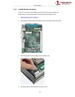
Страница 53: ... procedures below to install the mini PCIe module and SIM card as well as the antenna for wireless communication 1 Disassemble the system enclosure 2 The mini PCIe and USIM slot can be located once the enclosure has been removed 3 To install insert mini PCIe module s gold finger on a 45 degree angle into the socket gently press the module down and secure it with a screw ...

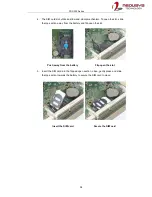
Страница 54: ...e the top section away from the battery and flip open the slot Push away from the battery Flip open the slot 5 Insert the SIM card into the flipped open section close gently press and slide the top section towards the battery to secure the SIM card in place Insert the SIM card Secure the SIM card ...

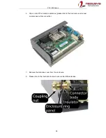
Страница 55: ... Clip on mini PCIe module s antennae please refer to the module s user manual on antennae cable connection 7 Remove the Antennae cover from the enclosure 8 Please refer to the illustration below to secure the SMA antennae ...

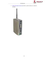
Страница 56: ...POC 300 Series 56 9 Reinstall the system enclosure and attach the external antennae to complete the installation ...

Страница 57: ...es motherboard Please follow the procedures below to install the half size mSATA module 1 Disassemble the system enclosure 2 The half size mSATA slot can be located once the enclosure has been removed 3 Insert the half size mSATA module on a 45 degree angle 4 Gently press the card down and secure with a screw ...

Страница 58: ...POC 300 Series 58 5 Reinstall the system enclosure ...

Страница 59: ...A port indicated in blue and the four support stands indicated in red 2 Match the 2 5 HDD SSD SATA connector to the SATA port on the module and gently insert the HDD SSD into place 3 Secure the 2 5 HDD SSD with the supplied four flathead screws The screws are inserted indicated in red from the same side as the MezIO connector indicated in blue 4 Once the 2 5 HDD SSD is secured the module is ready ...

Страница 60: ...the MezIO TM Module section For installation please refer to the following procedure 1 Disassemble the system enclosure 2 The MezIO TM module expansion slot can be located once the enclosure has been removed 3 The stand off hex bolts are shipped with MezIO module POC 300 comes with M3 P head screws Here we need to remove P head screws and replace them with stand off bolts ...

Страница 61: ...le onto the PCBA The MezIO TM port should engage if the three 3 standoffs and screw holes meet Then using the three 3 screws supplied secure the module by fastening a screw on each standoff 5 If you are installing a new MezIO TM module into your system you ll need to remove the I O shield opening for the connector 6 Reinstall the system enclosure ...

Страница 62: ...ll the system enclosure gently slide the L shaped enclosure back in place making sure the screw hole on the hinge sits on the inside Place enclosure back in place Make sure hinge sits on the inside 2 Complete installing the system enclosure by fastening five 5 screws ...

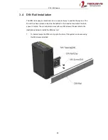
Страница 63: ...stem The Din rail has been proven to be most beneficial in the industrial environment where space is limited The mount plate comes with two M4 screws Please refer to the illustrations below to install the DIN clip rail 1 To install secure the DIN rail clip onto the rear of the system enclosure using the M4 screws provided ...

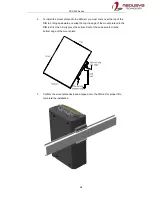
Страница 64: ...e DIN rail tilting downwards overlap the top clip edge of the mount plate onto the DIN rail first then firmly press the bottom front of the enclosure to clip the bottom edge of the mount plate 3 Confirm the mount plate has indeed clipped onto the DIN rail for proper fit to complete the installation ...

Страница 65: ...unt Bracket Installation with WM 300V 1 To install the full size wall mount bracket locate a flat surface area wall ceiling etc free from obstructions that meets the following dimensions NOTE All measurements are in millimeters mm ...

Страница 66: ...2 To install simply secure WM 300V wall mount bracket with the four M4 screws supplied onto the enclosure shown below 3 Once the wall mount bracket has been installed it is ready to be secured onto the dedicated location ...

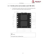
Страница 67: ...unt Bracket Installation with WM 300H 1 To install the full size wall mount bracket locate a flat surface area wall ceiling etc free from obstructions that meets the following dimensions NOTE All measurements are in millimeters mm ...

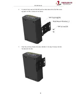
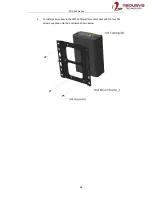
Страница 68: ...POC 300 Series 68 2 To install simply secure the WM 300H wall mount bracket with the four M4 screws supplied onto the enclosure shown below ...

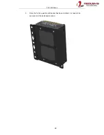
Страница 69: ...POC 300 Series 69 3 Once the full size wall mount bracket has been installed it is ready to be secured onto the dedicated location ...

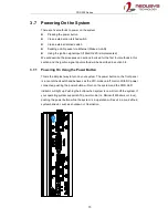
Страница 70: ...hod will be described in section 3 8 3 7 1 Powering On Using the Power Button This is the simplest way to turn on your system The power button on the front panel is a non latched switch and behaves as the ATX mode on off control With DC power connected pushing the power button will turn on the system and the PWR LED indicator will light up Pushing the button when system is on will turn off the sys...

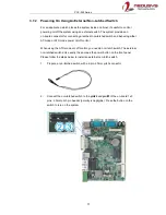
Страница 71: ...AT mode or ATX mode power on off control When using the ATX mode on off control you need a non latch switch The external non latched switch acts exactly the same as the power button on the front panel Please follow the steps below to install an external non latch switch 1 Prepare a non latched switch with a 2 pin 2 0mm pitch connector 2 Connect the non latched switch to the pin 2 and pin 3 of the ...

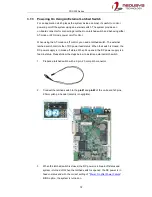
Страница 72: ...DC power feed status When the switch is closed the DC power supply is in break off status When it s opened the DC power supply is in feed in status Please follow the steps below to install an external latch switch 1 Prepare a latched switch with a 2 pin 2 0mm pitch connector 2 Connect the latched switch to the pin 1 and pin 2 of the on board 1x3 pins 2 0mm pitch pin header polarity is negligible 3...

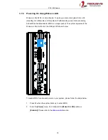
Страница 73: ...state via issuing Subnet Directed Broadcasts SDB or a magic packet The system implements the Wake on LAN function for the GbE port 3 shown below To enable WOL function and power on your system please follow the steps below 1 Press F2 when the system boots up to enter BIOS 2 Enter the Power menu And configure the Wake On LAN option as Enabled Please refer to the Wake on LAN section ...

Страница 74: ...es 74 3 In Windows systems identify the Local Area Connection of the corresponding Gigabit Controller and click the Configure button 4 Click the Power Management tag and check the following two options accordingly ...

Страница 75: ...78 D0 04 0A 0B 0C 78 D0 04 0A 0B 0C 78 D0 04 0A 0B 0C 78 D0 04 0A 0B 0C 78 D0 04 0A 0B 0C 78 D0 04 0A 0B 0C 78 D0 04 0A 0B 0C 78 D0 04 0A 0B 0C 78 D0 04 0A 0B 0C 78 D0 04 0A 0B 0C 78 D0 04 0A 0B 0C 78 D0 04 0A 0B 0C 78 D0 04 0A 0B 0C 78 D0 04 0A 0B 0C 78 D0 04 0A 0B 0C MISC CRC There are some free tools available on Internet that can be used to send a magic packet Please refer to the following lin...

Страница 76: ... starts to periodically detect ignition signal Note that only MCU is working at this moment and the overall power consumption is less than 2 mW 2 Ignition signal is active both 12VDC and 24VDC ignition signals are accepted 3 MCU starts to count a pre defined power on delay 4 Once power on delay expired MCU turns on necessary standby power for the system 3 3VSB 5VSB 5 A PWRBTN pulse is then issued ...

Страница 77: ...l module will cancel the power off delay process and keep the system running System hard off In some cases system may fail to shutdown via a soft off operation due to system application halts The ignition power control module offers a mechanism called hard off to handle this unexpected condition By detecting the system status it can determine whether the system is shutting down normally If not the...

Страница 78: ...rminal block shared with DC power input For in vehicle ignition control wiring please do the following 1 Connect car Battery line 12V for sedan 24V for bus truck to V 2 Connect car Batter GND line to GND 3 Connect ACC line to IGN WARNING Please make sure your DC power source and IGN signal share the same ground IGN input accepts 8 35VDC Supply a voltage higher than 35VDC may damage the system ...

Страница 79: ...ng the power button By default Windows 7 8 10 goes to sleep S3 mode when power button is pressed As sleep S3 is not a complete shutdown behavior the ignition control function does not recognize the finish of a normal shut down process and thus users will encounter a system hard off power cut off after 10 minutes Please configure When I press the power button to Shut down in your Windows system set...

Страница 80: ...t power on and power off delay User can only use the power button on the front panel to turn on or turn off the system Mode Power on Delay Power off Delay Hard off Timeout 0 N A N A N A Mode 1 Mode 1 is AT mode without power on and power off delay The system automatically turns on when DC power is applied A retry mechanism is designed to repeat the power on cycle if the system fails to boot up Mod...

Страница 81: ...s 1 minute 10 minutes 10 A 3 minutes 10 minutes 10 minutes 11 B 3 minutes 30 minutes 10 minutes 12 C 10 minutes 30 minutes 10 minutes Mode 13 D Mode 14 E Mode 13 and Mode 14 are ignition power control modes with very long power off delay Both modes support the feature of smart off delay which automatically detect system status during power off delay duration and cut off system power if system is o...

Страница 82: ...y In this section we ll illustrate some BIOS settings you may need to set or change prior to operating system installation Please always make sure you understand the effect of change before you proceed with any changes If you are unsure of the function you are changing it is recommended to change one setting at a time to see its effect s ...

Страница 83: ...transmission you may set the Slew Rate option as High to improve signal quality For RS 422 485 communication the RS 422 485 Termination option determines whether to enable disable internal termination of RS 422 485 transceiver according to your wiring configuration e g with or without external termination To set COM1 operating mode 1 Press F2 when the system boots up to enter the BIOS setup utilit...

Страница 84: ...22 485 transmission you may set the Slew Rate option as High to improve signal quality For RS 422 485 communication the RS 422 485 Termination option determines whether to enable disable internal termination of RS 422 485 transceiver according to your wiring configuration e g with or without external termination To set COM2 3 4 operating mode 1 Press F2 when the system boots up to enter the BIOS s...

Страница 85: ...ode offers bandwidth throughput of up to 600MB s For systems with only mSATA module installed Gen 2 is recommended For systems with MezIO R11 R12 and 2 5 SSD you can set this option to Gen2 Gen3 according to SSD s specifications To set Chipset SATA mode 1 Press F2 when the system boots up to enter the BIOS setup utility 2 Go to Advanced SATA Configuration 3 Set the SATA Interface Speed option to t...

Страница 86: ... CPU to wake up and be 100 operational Depending on your application you can configure these options to have higher performance disable C States or lower power consumption enable C States To set C States and Enhanced C States 1 Press F2 when the system boots up to enter the BIOS setup utility 2 Go to Power CPU Configuration CPU Power Management 3 Enable disable the C States option according to you...

Страница 87: ... Wake on LAN function you have to enable this option first in BIOS settings Please refer to Powering on via Wake on LAN function To enable disable Wake on LAN option 1 Press F2 when the system boots up to enter the BIOS setup utility 2 Go to Power 3 You may enable disable the Wake on LAN option 4 Once set press F10 to save setting and exit ...

Страница 88: ... operating state when DC power loss occurred When you want to use the AT mode remote on off control function you have to set this option to S0 Power On Please refer to section 3 7 2 for instructions of using AT mode remote on off control function To set Power On after Power Failure option 1 Press F2 when the system boots up to enter the BIOS setup utility 2 Go to Power 3 Set the Power On after Pow...

Страница 89: ...s the first device to boot or the last in the boot sequence To set the newly installed boot device as the first or last boot device 1 Press F2 when the system boots up to enter the BIOS setup utility 2 Go to Boot Add Boot Options menu 3 Select First or Last for your newly added boot device and press Enter 4 Once set press F10 to save setting and exit ...

Страница 90: ...ted the user must stop the watchdog timer once booted into the OS This guarantees the system can always boot into the OS otherwise another booting process will be initiated For information about programming watchdog timer please refer to Appendix A Using WDT DIO To set the watchdog timer for boot in BIOS 1 Press F2 when the system boots up to enter the BIOS setup utility 2 Go to Boot menu 3 Disabl...

Страница 91: ...or two set a default boot device in the BIOS To select a boot device in BIOS 1 When system boots up press F2 to enter BIOS setup utility 2 Go to Boot Boot Menu 3 The Boot Menu option determines whether to list all bootable devices connected to your system according to device or device type The default order of boot device type is Hard Disk Drive USB CD DVD ROM Driver Others You can use F5 F6 or to...

Страница 92: ... tested in Neousys Technology Inc Microsoft Windows 10 Professional 64 bit Microsoft Windows 10 IoT Enterprise 64 bit Ubuntu 16 04 3 LTS 4 10 kernel NOTE For Linux system user may need to manually compile and install the driver for Intel graphics or I210 GbE controller if the driver is not embedded in kernel You can visit Intel website for further information Neousys may remove or update operating...

Страница 93: ...cally please refer to the following procedures 1 Insert the Drivers Utilities DVD into a USB DVD drive connect to your system A setup utility launches and the following dialog appears 2 Click on Automatic Driver Installation and the setup utility will automatically detect your Windows operating system and install all necessary drivers The installation process takes about 6 8 minutes depending on y...

Страница 94: ...elow Windows 10 x64 The recommended driver installation sequence is 1 Chipset driver x Driver_Pool Chipset_10_APL Win_ALL SetupChipset exe 2 Graphics driver x Driver_Pool Graphics_SKL_APL Win_7_8_10_APL_64 Setup exe 3 Audio driver x Driver_Pool Audio_ALC262 Win_ALL_64 Setup exe 4 LAN driver x Driver_Pool GbE_I210_I350 Win_ALL_64 APPS PROSETDX Winx64 DxS etup exe 5 TXE driver x Driver_Pool TXE_APL ...

Страница 95: ...n prior to use these functions Please note that you must install WDT_DIO_Setup_v2 2 6 or later versions NOTE Please install WDT_DIO_Setup_v2 2 6 or later versions Windows 7 8 10 x64 Please execute the driver setup program in the following directory x Driver_Pool WDT_DIO Win7_8_10_64 WDT_DIO_Setup_v2 2 6 x64 exe Windows 7 8 10 WOW64 Please execute the driver setup program in the following directory...

Страница 96: ... supports Windows 10 x64 and WOW64 platform For other OS support please contact Neousys Technology for further information Installing WDT_DIO Library The WDT_DIO function library is delivered in the form of a setup package named WDT_DIO_Setup exe In prior to program WDT you should execute the setup program and install the WDT library Please use the following WDT_DIO_Setup packages according to you...

Страница 97: ...allation To setup WDT DIO Library please follow instructions below 1 Execute WDT_DIO_Setup 2 2 6 exe and the following dialog appears 2 Click Next and specify the directory of installing related files The default directory is C Neousys WDT_DIO ...

Страница 98: ...ry will take effect after the system has rebooted 4 When programming your WDT or DIO program the related files are located in Header File Include Library File Lib Function Reference Manual Sample Code Sample WDT_Demo Demo for Watchdog Timer Sample DIO_Demo Demo for isolated DIO Control Sample COS_Demo Demo for change of state DI ...

Страница 99: ...OOL SetWDT WORD tick BYTE unit Description Set timeout value and unit for watchdog timer When InitWDT is invoked a default timeout value of 255 seconds is assigned Parameter tick WORD value 1 65535 to indicate timeout ticks unit BYTE value 0 or 1 to indicate unit of timeout ticks 0 unit is minute 1 unit is second Return Value If value of unit is correct 0 or 1 this function returns TRUE otherwise ...

Страница 100: ...function returns TRUE otherwise FALSE Usage BOOL bRet StartWDT ResetWDT Syntax BOOL ResetWDT void Description Reset the timeout value to the value given by SetWDT If ResetWDT or StopWDT is not invoked before WDT countdowns to 0 the WDT expires and the system resets Parameter None Return Value Always returns TRUE Usage BOOL bRet ResetWDT StopWDT Syntax BOOL StopWDT void Description Stops the countd...

Страница 101: ...age for logic low is 0 1 5V The digital output function of System series is implemented using Power MOSFET Analog Device iCoupler component The DO channels are configured as NO normally open configuration When you turn on system all DO channels have a deterministic state of logic 0 circuit disconnected from GND return When logic 1 is specified MOSFET is activated and GND return path is established...

Страница 102: ...al output channel 1 10 ISO_DO0 O Digital output channel 0 11 VDD DO voltage source input for inductive load 12 ISO5V Isolated 5V power supply 13 Reserved Reserved pin Keep unconnected 14 ISO_DI3L Digital input channel 3 GND 15 ISO_DI2L Digital input channel 2 GND 16 ISO_DI1L Digital input channel 1 GND 17 ISO_DI0L Digital input channel 0 GND 18 Reserved Reserved pin Keep unconnected 19 Reserved Re...

Страница 103: ...adLine BYTE ch Description Read a single channel of isolated digital input Parameter ch BYTE value specifies the DI channel to be read ch should be a value of 0 3 Return Value The status TRUE or FALSE of the specified DI channel Usage BYTE ch 3 DI channel 3 BOOL DIChValue DIReadLine ch read DI channel 3 DIReadPort Syntax WORD DIReadPort void Description Read the entire isolated digital input port ...

Страница 104: ...ecifies the status of DO channel Return Value None Usage BYTE ch 3 DI channel 3 BOOL DOChValue TRUE DOWriteLine ch DOChValue write DO channel 3 as TRUE DOWritePort Syntax void DOWritePort WORD value Description Write the entire isolated digital output port 4 channels Parameter value WORD value specifies the status of the DO port value should be a value of 0 15 Return Value None Usage WORD DOPortVa...

Страница 105: ...fies the status of DO channel Return Value None Usage BYTE ch 3 DI channel 3 BOOL DOChValue TRUE DOWriteLineChecked ch DOChValue write DO channel 3 as TRUE DOWritePortChecked Syntax void DOWritePortChecked WORD value Description Write the entire isolated digital output port 8 channels and check it has been done Note that this function is not returned until the write value has been checked the same...

Страница 106: ...hat interrupt is generated when level change set to 0 or on rising falling edge set to 1 for the corresponding channel s edgeType WORD value specifies that interrupt is generated on rising edge set to 0 or falling set to 1 edge for corresponding channel s This value is neglected if edgeMode is set to 0 for the corresponding channel s cbSetup in The length of the structure in bytes The caller must ...

Страница 107: ...void __stdcall callback_func COS_INT_CALLBACK_ARG arg Return Value TRUE if setup successes FALSE if setup failed Usage void __stdcall callback_func COS_INT_CALLBACK_ARG arg printf data 0x 02x flag 0x 02x seq 02d n arg portData arg intrFlag arg intrSeq BOOL bRet RegisterCallbackDICOS callback_func StartDICOS Syntax BOOL StartDICOS void Description Start DI Change of State interrupt Parameter None R...

Страница 108: ...b h include windows h include WDT_DIO h Step 0 define a Change of State Interrupt callback function void __stdcall callback_function COS_INT_CALLBACK_ARG arg printf data 0x 02x flag 0x 02x seq 02d n arg portData arg intrFlag arg intrSeq int main int argc char argv Step 1 initialize DIO library by invoking InitDIO if InitDIO printf InitDIO FAILED n return 1 printf InitDIO PASSED n Step 2 setup Chan...

Страница 109: ... return 2 printf SetupDICOS PASSED n Step 3 register the callback function if RegisterCallbackDICOS callback_function printf RegisterCallbackDICOS FAILED n return 3 printf RegisterCallbackDICOS PASSED n Step 4 start the DI Change of State Interrupt if StartDICOS printf StartDICOS FAILED n return 4 printf StartDICOS PASSED n printf npress any key to stop n system pause nul Step 5 stop the DI Change...

Страница 110: ...POC 300 Series 110 printf StopDICOS PASSED n printf npress any key to exit n system pause nul return 0 ...

Отзывы: