


SECTION 2
INSTALLATION & SETUP
Media Thickness Adjustment
The printhead carriage height must be set to accommodate the thickness of the media you will be
feeding. This printer incorporates a servo motor to control the height of the carriage.
1.
Make sure the printer is off-line. If on-line, press the ONLINE key to take it off-line.
2.
Press the MENU key, then use the +key to scroll to the menu item “Media Thickness Setup”. Press
the ENTER key to select this feature.
3.
Turn the Media Thickness Dial [A] fully
clockwise. This will cause the servo motor
to raise the printhead carriage to its highest
position.
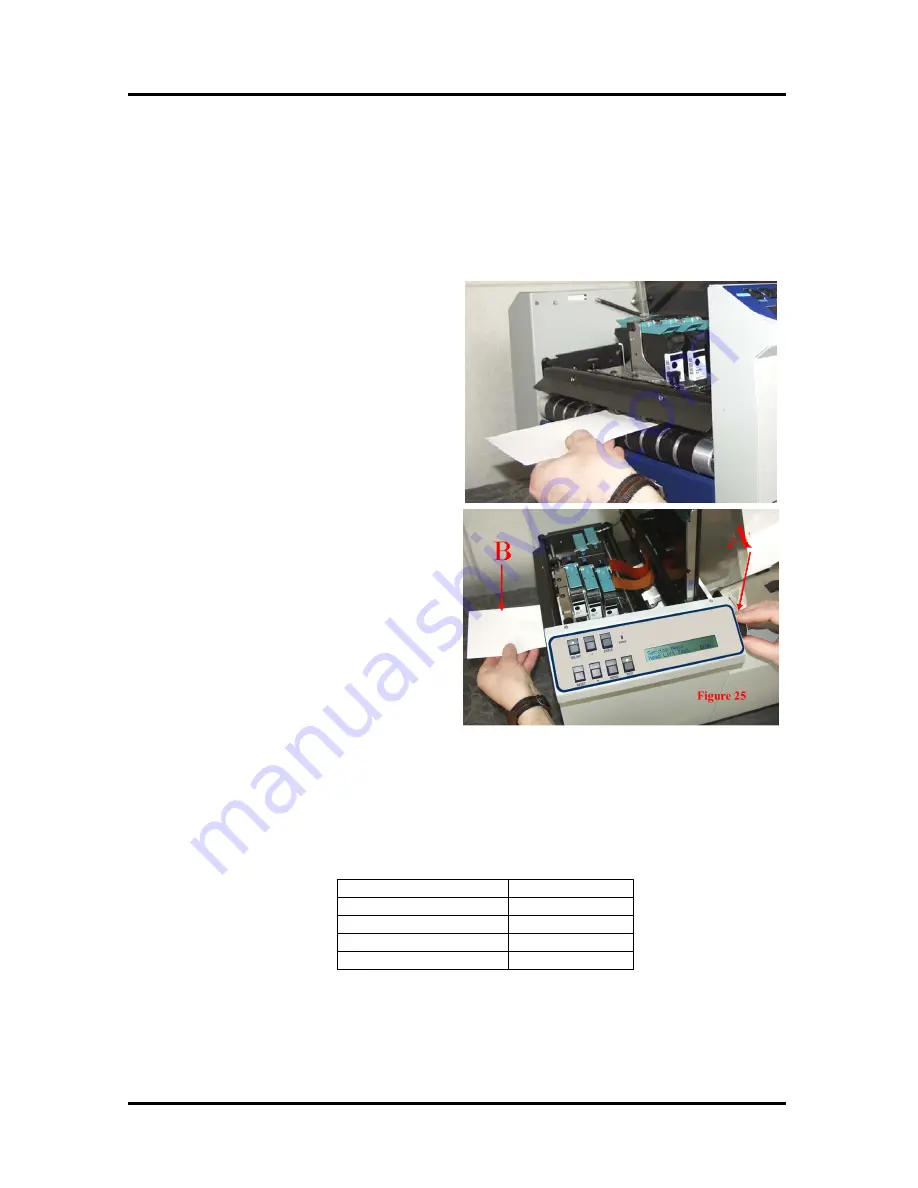
4.
Place a piece of media [B] under the
printhead carriage rollers, as shown in
.
Figure 25
5.
Slowly adjust the Media Thickness Dial [A]
counter-clockwise until the printhead
carriage rollers touch and hold the Media
[B] securely.
Figure 24
6.
When properly adjusted the Media [B] will
be securely captured between the printhead
carriage rollers and the lower transport
belts. It should require a moderate amount
of force to pull the Media [B] from under
the printhead carriage rollers.
Tip:
Make a note of the Media Thickness
Dial position, as a reference for future
adjustment when using this particular
media.
7.
Press the MENU button to exit out of the
“Media Thickness Setup” mode.
NOTE:
The printer will automatically raise the printhead carriage to its highest position, when you exit
the “Media Thickness Setup” mode. When the printer is told to print or feed material, it will
automatically lower the carriage to your preset value.
The chart below can be used as a general guideline for setting the position of the Media
Thickness Dial [A].
Media Thickness
Dial Setting
.004” to 1/32”
0 to 2
1/32” to 1/16”
2 to 3
1/16” to 1/8”
3 to 7
1/8” to 1/4”
7 to 10
NOTE:
The chart show general guidelines. It is best to adjust the carriage height using the
procedure outlined above.
© 2009 Neopost USA Inc. All rights reserved.
18
Содержание AS-940
Страница 1: ...AS 940 Addressing Solution Operating Guide...
Страница 12: ...SECTION 1 GETTING ACQUAINTED Notes 2009 Neopost USA Inc All rights reserved 12...
Страница 36: ...SECTION 3 OPERATING THE PRINTER Notes 2009 Neopost USA Inc All rights reserved 36...
Страница 42: ...Notes 2009 Neopost USA Inc All rights reserved 42...


