


16
temperature of the thermocouple in the area. If the thermocouple is closer to the
heating source, the displayed temperature will be relatively higher than the interval
temperature. The closer the thermocouple is to the direct channel of PCB, the
displayed temperature will be more able to reflect the interval temperature. It is
advisable to consult the oven manufacturer to understand clearly the relationship
between the displayed temperature and the actual interval temperature. In this
paper, the interval temperature rather than the display temperature will be
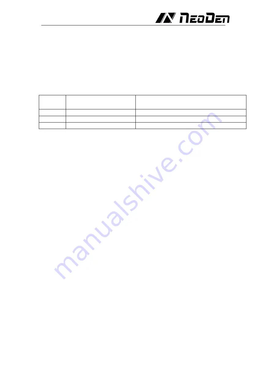
considered. Table 1 lists the interval temperature settings for typical PCB assembly
reflow.
Table 1. Typical PCB return zone temperature setting
I n t e r v a l
Interval temperature setting Actual plate temperature at the end of interval
Preheating
210
℃
140
℃
Activity
177
℃
150
℃
Reflow
250
℃
210
℃
The interval temperature is set to the actual plate temperature at the end of the
interval
After the speed and temperature are determined, they must be input to the oven
controller. Once all parameters are input, start the machine, and after the oven is
stable (i.e., all the actual displayed temperatures are close to the set parameters),
the wave can be started. The next PCB is placed in the conveyor belt, which
triggers the thermometer to start recording data.
For convenient using,some thermometer includes a trigger function to
automatically start the thermometer at a relatively low temperature, which is
typically slightly higher than the human body temperature of 37°C (98.6°F). For
example, the automatic trigger of 38°C (100°F) allows the thermometer to start
working as soon as the PCB is put on the conveyor chain and into the furnace, so
that the thermocouple will not be triggered by mistake when it is handled by the
human.
Once the initial temperature profile is generated, it can be compared with the
profile recommended by the solder paste manufacturer or the profile shown in
Figure 2.
First, it must be verified that the total time from the ambient temperature to the
peak temperature of the reflux is compatible with the desired stay time of the
heating curve. If it is too long, increase the conveyor speed proportionally; if it is
too short, decrease the conveyor speed proportionally.
In the next step, the shape of the temperature profile must be compared with the
desired one (Figure 2). If the shape is not compatible, then compare it with the
following figures (Figures 3-6). Choose the most compatible temperature profile
compared to the actual shape of the profile. Should consider the deviation from left
to right (process sequence). For example, if there is a difference between the
preheating and soldering zones, first adjust the difference in the preheating zone
correctly. Generally, it is best to adjust one parameter at a time and test in run
before making further adjustments.Because a change in a given zone will also
affect the results of subsequent zones. We also recommend that novices had better
make small adjustments. Once you gain experience on a particular oven, you will
have a better "feel" to make more big adjustments.