background image


6   Ethernet Network Setup B 


12 

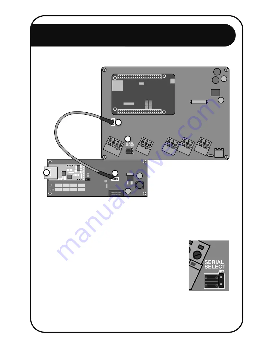
3.  For the FG7: 


a.  Disconnect the power and open the NEMTEK FG7 (Refer to the FG7 Installer 

Manual). 

b.  Connect the supplied FG7-Nemlink pigtail to the FG7 J7 connector. [1] 
c.  Connect the other end of the pigtail to the Nemlink J1 connector. [2] 
d.  Configure the SERIAL SELECT jumper JP7 to TTL. 

No other jumpers need to be changed. Refer to 
the Installer Manual for a complete list of jumper 
configurations. [3] 

e.  Close the FG7. 
f.  Connect the FG7 to a port on the ethernet switch (the 

port number does not matter) with an ethernet cable. [4] 

g.  Power up the FG7. 
h.  Configure the FG7 software by referring to the FG7 Installer Manual. 

1


4


3


2


Содержание Druid LCD 2X

Страница 1: ...Network Guide For Druid LCD 2X Energizers ...

Страница 2: ...ic Ethernet Setup 11 6 2 Ethernet Optic Fibre Network Setup 16 6 3 Ethernet Optic Fibre Ring Example 17 6 4 Ethernet Wireless Network Setup 18 7 RS485 Network 20 7 1 Daisy Chain Network Setup 20 7 2 Star Network Setup 27 7 3 RS485 Optic Fibre Network Setup 32 8 Ethernet Optic Fibre RS485 Combined Network 38 9 8 Way Smart IO Board Setup 40 Table of Contents 2 ...

Страница 3: ...s manual aims to provide a setup guide for these different topologies on hardware and software level All software mentioned in this guide can be found online at http www nemtek druid fenceprobe com All required hardware mentioned in this manual is available directly from NEMTEK 2 DISCLAIMER NEMTEK Holdings Pty Ltd or any of its subsidiary companies does not guarantee that the operation of the prod...

Страница 4: ... Africa CAPE TOWN Tel 27 0 21 386 3742 27B Concord Crescent Airport City Fax 27 0 21 386 5573 Cape Town South Africa NELSPRUIT Tel 27 0 13 752 2187 Waterval Ave Riverside Industrial Fax 27 0 13 752 2188 Nelspruit South Africa KWAZULU NATAL Tel 27 0 31 701 2125 19 Henwood Road Fax 27 0 31 701 2125 Pinetown South Africa AUSTRALIA Tel 08 9303 9855 Unit 5 19 Innovation Circuit Email nemtek bigpond net...

Страница 5: ... of both energizers will also be synchronised with this setup The master energizer will be displayed as Energizer 1 Zone 1 2 and the slave energizer as Energizer 2 Zone 3 4 on the keypad Follow the setup instructions chronologically with the corresponding number in the figure given after the steps in brackets 1 Set up the master energizer a Disconnect the energizer mains and battery power 1 2 b Co...

Страница 6: ...e energizer LCD display turns blue 4 h Disconnect the energizer mains and battery power 1 2 i Remove the keypad from the energizer 3 2 Set up the slave energizer a Disconnect the energizer mains and battery power 5 6 b Connect the keypad to the slave energizer and reset to factory default by following the same procedure as the master 7 c Configure all user preferences for example alarm bypasses sp...

Страница 7: ... together step 1 therefore two wires must be fastened together in the same terminal 3 7 b Connect the keypad s data line marked DATA to the same data line used to connect the master and slave energizers by connecting the wire to either the master or slave energizer Note the data terminal on both energizers were already used to connect the energizers together step 1 therefore two wires must be fast...

Страница 8: ...elow 3 Connect the Ethernet Module directly to your computer using a suitable Ethernet cable 4 Power up the NEMTEK board and ensure the green POWER LED is lit For the NemLink board power the board via either the J1 or J2 connector 5 Run the USR M0 setup software on your computer 6 Click on the Search Device button 7 A device should appear in the dialog box above the Search Device button If no devi...

Страница 9: ... Ethernet Module connected to an FG7 or 8 way Smart IO Board and the device is installed on a local private network the Module work mode needs to be changed to UDP The ModuleStaticIP and RemoteIP need to be changed as explained in step 13 and 14 12 Large public networks including routing and remote access via an internet connection are not covered by this guide Please consult your network administ...

Страница 10: ...refore the RemoteIP must be identical to the ModuleStaticIP of the energizer it communicates with c With reference to the ModuleStaticIP addresses in the example in step 13 the following is an example of valid RemoteIP addresses on the same network i NEMTEK NemLink connected to NEMTEK FG7 192 168 0 255 ii NEMTEK NemLink connected to Energizer not required iii NEMTEK 8 way Relay Board not required ...

Страница 11: ...not possible The NEMTEK Power Pack may be used to provide a 12V supply with battery backup to the FG7 and 8 way Relay Board Note that all ethernet cables should have a maximum length of 100m and the FG7 Nemlink pigtail and 10 way ribbon should have a maximum length of 1m To set up the network successfully follow these steps 1 Configure all Ethernet Modules installed on the Nemlinks and 8 way Relay...

Страница 12: ...the pigtail to the Nemlink J1 connector 2 d Configure the SERIAL SELECT jumper JP7 to TTL No other jumpers need to be changed Refer to the Installer Manual for a complete list of jumper configurations 3 e Close the FG7 f Connect the FG7 to a port on the ethernet switch the port number does not matter with an ethernet cable 4 g Power up the FG7 h Configure the FG7 software by referring to the FG7 I...

Страница 13: ...lay turns purple 6 g Configure the network address from by entering 51xx where xx is the address from 1 to 32 Energizer addresses must be chronologically configured starting at 1 For example three energizers on a network with addresses 5 18 and 22 is not allowed as they need to be addressed 1 2 and 3 Relay boards and energizers are addressed separately from 1 to 32 h Exit installer mode by enterin...

Страница 14: ...xample 3 boards in the network with addresses 3 6 and 20 is not allowed as their addresses must be 1 2 and 3 Relay boards and energizers are addressed separately from 1 to 32 Relay boards and energizers are addressed separately from 1 to 32 On the FG7 module an address offset of 32 is added to all relay boards Therefore relay board 1 will be referred to as 33 1 32 relay board 2 as 34 2 32 etc on t...

Страница 15: ...Configure passive synchronisation GPS synchronisation by entering 5031 g Exit installer mode by entering Ensure the energizer LCD display turns blue 5 h The red SYNC LED on the GPS module will start flashing if a GPS signal was obtained The time to obtain a signal will vary depending on the signal strength Ensure the GPS module is not obstructed to the sky by metal or thick concrete structures whi...

Страница 16: ...ure below The ethernet signals are converted to and from optic signals by using a pair of ethernet optic fibre converters Either Single Mode converters and cable with a maximum distance of 20km or Multi Mode converter and cable with a maximum distance of 2km may be used These converters require a 12V dc power supply which can be supplied by the NEMTEK Power Pack The rest of the network configurati...

Страница 17: ...tches This is useful when optic fibre cables are installed along the perimeter fence wall and energizers or IO boards need to be installed consecutively near the fence wall More than one energizer or IO board can be installed on any ethernet switch as long as the total number of energizers and IO boards in the network are both less or equal than 32 Note the power supplies were omitted but can be i...

Страница 18: ...placed with wireless technology for ease of installation Different topologies are possible depending on the client s requirements as shown in the figures below The software setup explained in this document will be identical for the different topologies Note that all antennas depicted have built in radios 18 ...

Страница 19: ... network devices and all antenna should have a unique static IP Don not use DHCP See section 5 of this document for further details b Subnet mask Should be in the same as the rest of the NEMTEK network devices recommended 255 255 255 0 See section 5 of this document for further details c Network mode all antennas Bridge d Wireless mode antenna on FG7 side Access point e Wireless mode antenna on en...

Страница 20: ...l be used if required 7 1 Daisy Chain Network Setup The example diagram below illustrates the required hardware and wiring required for an RS485 daisy chain network setup The NEMTEK Power Pack may be used to provide a 12V supply with battery backup to the FG7 and 8 way Relay Board Note that all RS485 3 core cables should have a maximum length of 1000m and the 10 way ribbon should have a maximum le...

Страница 21: ...the previous RS485 network device to the RS485 IN GND A and B terminals of the FG7 1 c Connect the GND A and B wires going to the next RS485 network device to the RS458 OUT GND A and B terminals of the FG7 2 d Configure the LINE BIAS jumper JP1 to DISABLE 3 e Configure the RX EN and TX EN jumpers JP2 and JP3 to ENABLE 4 f Configure the SERIAL SELECT jumper JP7 to RSXXX 5 g Configure the RSXXX jump...

Страница 22: ...ypad to the energizer 5 e Connect the GND A and B wires coming from the DATA OUT of the previous RS485 network device to the DATA IN GND marked G A and B terminals of the RS485 board 6 f Connect the GND A and B wires going to the next RS485 network device to the DATA OUT GND marked G A and B terminals of the RS458 board 6 g Configure jumpers JP1 JP2 JP3 JP5 and JP6 like in the figure on the right ...

Страница 23: ...be chronologically configured starting at 1 For example three energizers on a network with addresses 5 18 and 22 is not allowed as they need to be addressed 1 2 and 3 Relay boards and energizers are addressed separately from 1 to 32 k Exit installer mode by entering Ensure the energizer LCD display turns blue 8 l Ensure the energizer network address is displayed on the LCD 8 m Route the cables out...

Страница 24: ... and energizers are addressed separately from 1 to 32 On the FG7 module an address offset of 32 is added to all relay boards Therefore relay board 1 will be referred to as 33 1 32 relay board 2 as 34 2 32 etc on the FG7 4 e Ensure jumpers JP5 B and C are populated Jumpers JP5 A and D can either be populated or not 5 f Connect the GND A and B wires coming from the DATA OUT of the previous RS485 net...

Страница 25: ...l be used as the master for synchronisation Connect a single core wire from the master energizer s sync terminal marked SYNC to the synchronisation input terminal marked IN of the RS485 board 1 2 c Connect the SYNC GND A and B wires going to the next energizer s RS485 synchronisation terminals to the SYNC OUT GND marked G A and B terminals of the master energizer s RS485 board 3 d Configure jumper...

Страница 26: ...nnect the SYNC OUT terminals to the first energizer 3 i Connect the SYNC GND A and B wires coming from the previous energizer s RS485 synchronisation terminals to the SYNC IN GND marked G A and B terminals of the energizer s RS485 board 3 j Enter installer mode by entering 012345 0 on the keypad Ensure the energizer LCD display turns purple 6 k Enter 5030 to put the slave energizer in passive sync...

Страница 27: ... RS485 5 core cables should have a maximum length of 1000m and the 10 way ribbon should have a maximum length of 1m It is recommended that the 5 core cables for RS485 communication are shielded and that the shields are grounded only at one end of the cable to prevent ground loops To set up the network follow these steps 1 For the connection setup between the PC and FG7 module refer to the FG7 inst...

Страница 28: ...network device OUT terminals as explained in steps 3 and 4 to the RS485 IN A and B terminals of the FG7 Since more than one network device may be connected to the FG7 it will be necessary to add all the wires together in the same screw terminal The ground wire does not need to be connected in this step 2 d Configure the LINE BIAS jumper JP1 to ENABLE 3 e Configure the RX EN and TX EN jumpers JP2 a...

Страница 29: ... energizer 5 e Connect the GND A and B wires coming from the DATA OUT of the FG7 to the DATA IN GND marked G A and B terminals of the RS485 board 6 f Connect the A and B wires coming from the DATA IN of the FG7 to the DATA OUT A and B terminals of the RS485 board It is not necessary to connect the GND terminals in this step 6 g Configure jumpers JP1 JP2 JP3 JP5 and JP6 like in the figure on the ri...

Страница 30: ...be chronologically configured starting at 1 For example three energizers on a network with addresses 5 18 and 22 is not allowed as they need to be addressed 1 2 and 3 Relay boards and energizers are addressed separately from 1 to 32 k Exit installer mode by entering Ensure the energizer LCD display turns blue 8 l Ensure the energizer network address is displayed on the LCD 8 m Route the cables out...

Страница 31: ...parately from 1 to 32 On the FG7 module an address offset of 32 is added to all relay boards Therefore relay board 1 will be referred to as 33 1 32 relay board 2 as 34 2 32 etc on the FG7 4 e Ensure jumpers JP5 C is populated and JP5 B not Jumpers JP5 A and D can either be populated or not 5 f Connect the GND A and B wires coming from the DATA OUT of the FG7 to the DATA IN GND A and B terminals of...

Страница 32: ...imum distance of 2km may be used These converters require a 12 Vdc power supply not shown in figure which can be supplied by the NEMTEK Power Pack The diagrams below show the different possible optic fibre configurations Note the wiring from the RS485 Fibre converter to the energizers or relay boards must be in a star topology and will not function correctly if wired in a daisy chain topology To s...

Страница 33: ...on the FG7 side a Connect the GND A and B wires coming from the output of the FG7 to the GND RX and RX of the first RS485 fibre converter b Connect the GND TX and TX wires to the next RS485 fibre converter s GND RX and RX terminals to form a chain c Connect the GND A and B wires going to the input of the FG7 to the GND TX and TX of the last RS485 fibre converter to complete the chain d Connect the...

Страница 34: ...rgizer Set up the energizer by following the steps in section 7 2 and replacing the FG7 with the RS485 fibre converter The converter s TX and TX terminals are the same as the FG7 s RS485 Output A and B terminals The converter s RX and RX terminals are the same as the FG7 s RS485 Input A and B terminals 6 For the RS485 8 way Relay Board Set up the relay board by following the steps in section 7 2 a...

Страница 35: ...MTEK Fenceprobe software 2 For the FG7 a Set the FG7 up by following the steps in section 7 2 b Connect the GND RX and RX wires going to all RS485 fibre converters to the RS458 OUT GND A and B terminals of the FG7 see FG7 figure in section 7 2 c Connect the GND TX and TX wires coming from all the RS485 fibre converters to the RS485 IN GND A and B terminals of the FG7 see FG7 figure in section 7 2 ...

Страница 36: ...rter at the energizers or relay boards to the TX port d Connect the fibre optic cable going to the TX port of the RS485 fibre converter at the energizers or relay boards to the RX port 4 For the RS485 fibre converters on the energizer relay board side Set up the RS485 fibre converters as explained in step 4 of the previous topology 5 For the Druid LCD 2x Set up the energizer as explained in step 5...

Страница 37: ...y be one RS485 fibre converter per network device FG7 Energizer Relay board in this topology but all wiring can be done as explained in the previous topology except for the fibre connections 3 Connect the converters optic fibre ports in a daisy chain topology making sure the previous converter s TX port is connected to the next converter s RX port The last converter s TX port will must be connecte...

Страница 38: ...should have a maximum length of 100m 1000m and 1m respectively It is recommended that the 5 core cables for RS485 communication are shielded and that the shields are grounded only at one end of the cable to prevent ground loops To set up the network follow these steps 1 For the connection setup between the PC and FG7 module refer to the FG7 installer manual The PC to FG7 link is optional to run th...

Страница 39: ...and B wires coming from the DATA IN of all the network devices in this network section to the DATA OUT A marked AL_IO and B marked BL_IO terminals of the Nemlink Network IO board It is not necessary to connect the GND terminals in this step Since more than one network device may be connected to this board it will be necessary to add all the wires together in the same screw terminal 3 e Connect the...

Страница 40: ... of the energizer or 8 way Relay Board by using the software application The figure below shows the possible connections Although the boards and energizers are connected on an Ethernet network in the third diagram every Smart IO Board can only communicate to one energizer The ethernet link between the two network switches can be replaced with an optic fibre link if longer distances are required Th...

Страница 41: ...Populate jumper JP7 A to put the board in programming mode 3 d Jumper JP7 C is only used when the board is connected to a Druid energizer When the jumper is populated the Smart IO board will force the state of its inputs onto the energizer and no changes will be possible on the energizer itself When the jumper is not populated changes are possible on the energizer and the Smart IO board will only ...

Страница 42: ...ill be connected to an energizer map the energizer status and alarms to the Smart IO relay outputs by ticking appropriate boxes The Smart IO Board Inputs are preconfigured to activate certain functions on the energizer and can t be changed For more detail refer to the Smart IO board manual n If the Smart IO board will be connected to an 8 way Relay Board map the 8 way Relay Board inputs to the Sma...

Страница 43: ...er Set up the energizer by following the steps in section 6 1 and setting the energizer address to 1 9 For the Ethernet 8 way Relay Board Set up the relay board by following the steps in section 6 1 and setting the board address to 1 Rev 1 0 5 June 2018 Print Code ...

Отзывы: