background image

Oxinet III

39

M a i n t e n a n c e

Service

If service is needed for any of the Oxinet III system components, contact qualified 

service personnel or your local Nellcor representative.
The Pager requires periodic replacement of the battery. Refer to the operator’s 

manual for battery replacement instructions. The latest version of the operator’s 

manual is available online at: 

http://www.mallinckrodt.com/respiratory/resp/Serv_Supp/ProductManuals.html 

Note:  

The Oxinet III software performs database maintenance automatically. The 

software temporarily closes the program, performs database file maintenance, and 

relaunches the program at 10:05 am every day. This maintenance procedure 

normally takes less than 45 seconds to run. 

During this brief period, the system 

does not process any incoming data, including alarms. 

To manually initiate the 

database maintenance process, refer to the section 

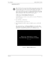
Maintenance (F11)

 on page 37 

of the Administrative Functions chapter in this manual.

Periodic Safety Checks

It is recommended that the following checks be performed on the transmitter 

every 24 months:
• Inspect the transmitter for mechanical and functional damage
• Inspect the relevant safety labels for legibility
If the labels are not legible, call Nellcor’s Technical Services Department at 

1.800.635.5267 or contact your local Nellcor representative. 

Cleaning

Caution: Do not spray, pour, or spill any liquid on any of the Oxinet III 

components, its accessories, connectors, switches, or openings in the chassis, 

since this may damage the Oxinet III system.

To clean the pager or Central Station screens, use a clean cloth designed for use on 

lenses or touch-sensitive screens. To clean the pager or Central Station casings, 

use a clean damp cloth and wipe dry. 
For surface-cleaning and disinfecting the transmitter, follow your institution’s 

procedures or:
• Surface-clean by using a soft cloth dampened with either a commercial, 

nonabrasive cleaner or a solution of 70% alcohol in water, and lightly wipe the 

surfaces of the transmitter.

Содержание Oxinet III

Страница 1: ...Service Manual C M Y CM MY CY CMY K 10005096_A_Oxinet III_PC_ServMan_Front Cover ai 10 6 05 10 01 53 AM 10005096_A_Oxinet III_PC_ServMan_Front Cover ai 10 6 05 10 01 53 AM...

Страница 2: ...ess or implied license under any Nellcor Puritan Bennett patent to use the instrument with any sensor that is not manufactured or licensed by Nellcor Puritan Bennett Covered by one or more of the foll...

Страница 3: ...r Switch 12 Connect the Router Switch to the Central Station 13 Connect the Central Station to Pager Transmitter Optional 13 Connect the Printer to the Central Station 13 Wireless Configuration 15 Con...

Страница 4: ...enu 32 Rooms Menu 35 Schedule Snap Shot Menu 36 Maintenance F11 37 To Manually Initiate Database Maintenance 37 Maintenance Service 39 Periodic Safety Checks 39 Cleaning 39 Spare Parts 40 Returning Co...

Страница 5: ...Backup Function 24 Figure 12 Backup in Progress 24 Figure 13 Backup in Progress Done 25 Figure 14 Backup Completed 25 Figure 15 Backup Restore Wizard 26 Figure 16 Backup Restore Function Select an Ac...

Страница 6: ...tion Keys Explained 20 Table 5 Alarms Settings 32 Table 6 Parts List 40 Table 7 Accessories List 40 Table 8 Troubleshooting 43 Table 9 Central Station 47 Table 10 Transmitter 48 Table 11 Access Point...

Страница 7: ...o replace any part of the hospital s device monitoring procedures including procedures regarding bedside pulse oximeters and responding to beside oximeter alarms Do not rely on the Oxinet III system a...

Страница 8: ...in the chassis since this may damage the Oxinet III system The transmitter pager or any other system component must be removed from service if they ever become submerged in liquid To ensure accurate p...

Страница 9: ...or executed on the application server Notes Notes are identified by the Note symbol shown above Notes contain important information that may otherwise be overlooked or missed Manual Overview This manu...

Страница 10: ...Introduction Service Manual 4 Oxinet III...

Страница 11: ...including procedures regarding bedside pulse oximeters and responding to beside oximeter alarms Do not rely on the Oxinet III system as the sole source of oximeter alarms The intended patient populat...

Страница 12: ...systems are listed below Wireless Configuration Pulse Oximeter suitable for use within the patient environment Transmitter suitable for use within the patient environment Access Point Router Switch Ce...

Страница 13: ...iguration Figure 2 all pulse oximeters are connected to a Communication Server generally the pulse oximeters are connected to a port in the wall which connects to the Communication Server housed in a...

Страница 14: ...by the clinician Pagers Use of pagers with the Oxinet III system is optional since patients are being continuously monitored at the Central Station If you decide to assign pagers to a patient you shou...

Страница 15: ...en forwards the data to the Central Station application server Central Station application server The Central Station application server which includes the computer that runs the Oxinet III software d...

Страница 16: ...s received from the connected router switch and if the optional paging feature is used sends the alarm data to the pager transmitter for transmission to the assigned pagers Pager Transmitter optional...

Страница 17: ...al Station or a computer monitor or hissing popping sounds coming from speakers If either of these symptoms occur increase the distance between the pager transmitter and the device experiencing the sy...

Страница 18: ...jack on the back of each Oximeter and plug the other end into AC power outlet 3 Connect a Cat5 Patch cable from the DB15M RJ 45 connector of each Oximeter to an available serial port on the back of t...

Страница 19: ...nnector on the Pager Transmitter Figure 3 3 Connect the Central Station s antenna as shown in Figure 3 4 Connect one end of the two ended RS 232 serial cable to the COM1 serial port of the Central Sta...

Страница 20: ...Installation Service Manual 14 Oxinet III Figure 3 Wired Configuration System Connection...

Страница 21: ...jack on the back of the Access Point to any of the numbered RJ 45 LAN ports on the back of the Router Switch Figure 4 2 Connect the Access Point Antenna to the Primary Antenna Connector on the back of...

Страница 22: ...triped connector is positive 2 Plug the barrel connector into the round power jack on the Access Point 3 Connect the opposite end of the power cable to terminal blocks on the power distribution panel...

Страница 23: ...al Station via the DC power cable and connect the mouse and keyboard to the Central Station Figure 4 Connect the Printer to the Central Station You need to connect a printer to the Central station in...

Страница 24: ...Installation Service Manual 18 Oxinet III Figure 4 Wireless Configuration System Connection...

Страница 25: ...provided in this chapter There are two ways to gain access to the Administrative functions either via an externally connected keyboard or by using the on screen touchscreen keyboard You may also want...

Страница 26: ...on the keyboard to refresh the screen A screen refresh can also be performed by touching the Oxinet III logo on the lower tool bar Aligning the Touchscreen F7 Alignment of the touchscreen is necessar...

Страница 27: ...complete press or click the OK button on the Elo Touchscreen Properties dialog box to close this function and return to the Main Display screen Adjusting Volume F8 This password protected function en...

Страница 28: ...en you have completed the volume adjustments press or click the X in the upper right corner of the Volume Control dialog box to close this function and return to the Main Display screen Using Backup R...

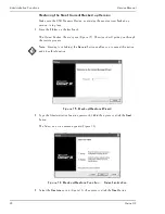
Страница 29: ...reen appears Figure 10 Figure 10 Backup Restore Function Select an Action The system determines if the USB Memory Device is installed If the device is installed the Backup Device Detected message appe...

Страница 30: ...on 3 Press or click the Next button The system begins the backup process and displays the message Backup in Progress Figure 12 The desktop outside the Backup screen will be black Figure 12 Backup in P...

Страница 31: ...ve Functions Oxinet III 25 Figure 13 Backup in Progress Done 5 Press or click the Next button The final message Backup Completed is displayed Figure 14 Figure 14 Backup Completed 6 Click the Finish bu...

Страница 32: ...Figure 15 The wizard will guide you through the restore process Note Pressing or clicking the Cancel button enables you to cancel this action and close this function Figure 15 Backup Restore Wizard 2...

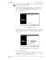
Страница 33: ...ss or click the Next button Figure 17 Restore Function 5 If you have more than one version backed up the system asks you to select the version you want to restore the most recent version will be the c...

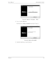
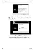
Страница 34: ...net III Figure 19 Restore Function Confirm the Version 8 The system begins the backup process and displays the message Restore in Progress Figure 20 Figure 20 Restore in Progress When the backup proce...

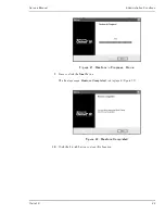
Страница 35: ...Functions Oxinet III 29 Figure 21 Restore in Progress Done 9 Press or click the Next button The final message Restore Completed is displayed Figure 22 Figure 22 Restore Completed 10 Click the Finish...

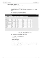
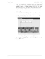
Страница 36: ...or click the Ok button The Oxinet Control Panel opens Figure 23 Figure 23 Oxinet Control Panel The Oxinet Control Panel menus enable you to Change the various alarm settings Add delete pagers Modify t...

Страница 37: ...iption abbreviation and level 1 To change settings in the Workstation Audible Central Station Tone Send Page or Snap Shot columns press or click within the cell for the setting you want to change A dr...

Страница 38: ...ager can be edited by a Nellcor Service technician only Level The settings in this column determines the priority level of an alarm Low or High can be edited by a Nellcor Service technician only Works...

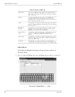
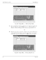
Страница 39: ...ion will occur 30 seconds after the initial page occurs if no one responds to the initial alarm page to either silence the alarm at the oximeter or resolve the reason for the alarm To Add a Pager 1 Pr...

Страница 40: ...le 103A50 Figure 27 the pager number is indicated on the back of the pager in this example the pager number is 103 OR 3B If the Oxinet III system is connected to a SMTP e mail system on the hospital s...

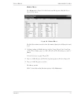
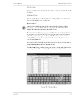
Страница 41: ...ke any necessary changes to the list The Unit column enables you to group rooms beds in categories that make sense for your facility If you have multiple Units in the system buttons representing each...

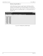
Страница 42: ...refer to the Running Reports chapter of the operator s manual for more information about Snapshots Press or click the check box next to the desired time to select or clear it For example in Figure 30...

Страница 43: ...s To manually initiate the database maintenance process perform the following procedure To Manually Initiate Database Maintenance Use the F11 function to manually initiate database maintenance This fu...

Страница 44: ...Administrative Functions Service Manual 38 Oxinet III...

Страница 45: ...e 37 of the Administrative Functions chapter in this manual Periodic Safety Checks It is recommended that the following checks be performed on the transmitter every 24 months Inspect the transmitter f...

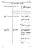
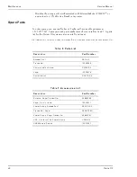
Страница 46: ...em is also available online at http www mallinckrodt com respiratory resp Serv_Supp apartweb main partaccemenu html Table 6 Parts List Description Part Number Access Point APOXI3 Transmitter 10006088...

Страница 47: ...oods authorization RGA number They will also provide you with the address for returning the Oxinet III component 2 Pack the component s The best method for returning the component s is to pack them in...

Страница 48: ...Maintenance Service Manual 42 Oxinet III...

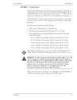
Страница 49: ...launches the program at 10 05 am every day This maintenance procedure normally takes less than 45 seconds to run During this brief period the system does not process any incoming data including alarms...

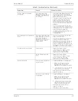
Страница 50: ...the communication server has power Check the connection between the communication server and the router switch Wireless configuration Check that the transmitter has power Check the connection between...

Страница 51: ...ter Check the cord connecting the Central Station to the pager transmitter to ensure it is securely connected to the serial port of the pager transmitter and the COM1 port of the Central Station The C...

Страница 52: ...s or a service manual contact Nellcor s Technical Services Department at 1 800 635 5267 or your local Nellcor representative The latest versions of this operator s manual and the service manual are av...

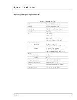
Страница 53: ...Parallel port 8 USB ports 1 Network Ethernet 10 100 port Physical Dimensions Computer 13 W x 4 H x 15 D 330 mm W x 102 mm H x 381 mm D Display 17 inch LCD Touchscreen 19 W x 19 H x 16 D 483 mm W x 483...

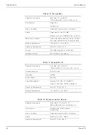
Страница 54: ...Altitude 0 to 3048 meters 0 to 10 000 feet Relative Humidity 5 to 95 non condensing Table 11 Access Point Physical Dimensions 7 75 Wx 1 25 H x 5 5 D 196 9 mm W x 31 7 mm H x 139 7 mm D Frequency Rang...

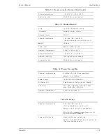
Страница 55: ...Humidity 5 to 90 non condensing Table 14 Pager Transmitter Physical Characteristics 8 5 W x 8 5 H x 2 D wall mountable Weight 1 5 lb 0 68 oz Power Supply 12 VDC 2 A AC DC Adapter RF Power Out 5 watts...

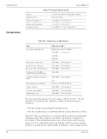
Страница 56: ...erence to radio communications Display 2 Line Alphanumeric display 36 character Display Lighting Button activation Storage Temperature 20 to 60 C 4 to 140 F Operating Temperature 10 to 50 C 14 to 122...

Страница 57: ...wered by AC Y Cord N 595 with Oxinet III transmitter both AC powered by AC Y Cord N 550 with Oxinet III transmitter both AC powered by AC Y Cord N 560 with Oxinet III transmitter both AC powered by AC...

Страница 58: ...Specifications Service Manual 52 Oxinet III...

Страница 59: ...king up restoring system configuration F9 22 Battery pager life 49 C Cautions 2 Central Station specifications 47 Cleaning 39 Communication Server specifications 48 Compliance Information 50 Component...

Страница 60: ...Shot 36 Schedule Snapshots 36 Service 39 single Access Point DC power connection 15 Space requirements 11 Spare Parts 40 specifications access point 48 central station 47 communication server 48 page...

Страница 61: ......
Страница 62: ...2005 Nellcor Puritan Bennett Inc All rights reserved 10005096A 1205 Tyco Healthcare Group LP Nellcor Puritan Bennett Division 4280 Hacienda Drive Pleasanton CA 94588 U S A...

Отзывы: