background image


 Docking and Undocking   2-3

4. 

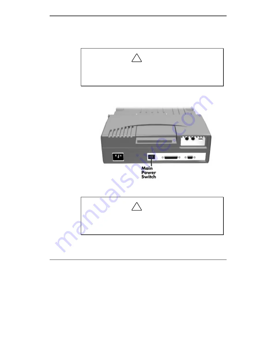
Locate the main power switch on the back of the MiniDock. Press the
white dot on the switch to turn on MiniDock power. A vertical line icon
above the power switch indicates power on.


!

CAUTION

 Make sure the Main Power switch on the back of the MiniDock is
powered on before docking the NEC Versa. Docking the NEC Versa
while the MiniDock is powered off can result in a system crash.

 Powering on the MiniDock


!

CAUTION

 Disconnecting the power cable, turning off power by pressing the
Main Power switch, or experiencing a power outage while running
the MiniDock and NEC Versa can result in a system crash.


Содержание VERSA MINIDOCK 6000

Страница 1: ... with the terms of the Warranty Statement accompanying each product However actual performance of each such product is dependent upon factors such as system configuration customer data and operator control Since implementation by customers of each product may vary the suitability of specific product configurations and applications must be determined by the customer and is not warranted by NECCSD T...

Страница 2: ... and how to care for the unit Chapter 2 provides instructions for docking and undocking an NEC Versa on the MiniDock Chapter 3 explains setting up the software to use your MiniDock and NEC Versa together Chapter 4 details how to connect external devices and add options to the MiniDock Chapter 5 directs you through basic troubleshooting procedures to help you solve problems that may arise Appendix ...

Страница 3: ...opic being discussed Names of keys are printed as they appear on the keyboard for example Ctrl Alt or Enter Text that you must type or keys that you must press are presented in bold type For example type dir and press Enter RELATED DOCUMENTS See the following documents for information related to the NEC MiniDock 6000 and NEC Versa operation The NEC MiniDock 6000 Quick Setup sheet Your NEC Versa us...

Страница 4: ...ck 6000 Care 1 9 Precautions 1 9 Routine Care 1 10 Battery Charging 1 10 2 Docking and Undocking Connecting the Power Cable 2 1 Preparing the NEC Versa for Docking 2 4 Docking the NEC Versa 2 6 Undocking the NEC Versa 2 11 3 Setting Up and Using the Software Using the Setup Utility 3 1 4 Adding Options and Connecting Peripherals Using the MiniDock VersaBay II 4 2 Installing a Device in the VersaBa...

Страница 5: ...Mouse 4 10 USB Devices 4 12 External Audio Options 4 13 External FDD Connector 4 14 Serial Devices 4 15 MIDI Game Devices 4 16 5 Solving Problems Problem Checklist 5 1 Troubleshooting 5 1 Replacing the Battery 5 2 Battery Precautions 5 5 Battery Disposal 5 5 If You Need Help 5 6 A Specifications and Environment B Pin Assignments Keyboard and Mouse Ports B 1 Serial Port B 2 Parallel Port B 3 Monito...

Страница 6: ...ick to the MIDI Game port and you re ready to work hard or play Undock the NEC Versa from the MiniDock and you re ready for the road This chapter introduces MiniDock features guides you to setting up in the correct environment and describes how to take care of the unit CARTON CONTENTS Carefully unpack and check the contents of the MiniDock 6000 carton Make sure you have the hardware components sho...

Страница 7: ...ecific Use an H05VV F or H05VVH2 F cable that is less than 15 feet 4 5 m long Use connector type EN60320 MiniDock FEATURES MiniDock features are found on every surface of the unit To become famil iar with these features read each of the following sections Front and Top The following figure shows the features found on the front and top of the MiniDock Descriptions of these features follow the figur...

Страница 8: ...C Port Guard The adjustable AC port guard keeps you from acci dentally docking the NEC Versa while it is still plugged into the AC adapter When the notebook is docked the MiniDock supplies power to run the system and charges the battery installed in the NEC Versa Notebook Glide This panel allows your notebook computer to glide easily towards the docking connector during docking and away from the c...

Страница 9: ...red on or an eject request was accepted and the computer is ready for undocking IDE Drive Access lights green when a CD ROM hard disk or SuperDisk LS 120 drive installed in the MiniDock or NEC Versa is accessed Diskette Drive Access lights green when a standard diskette drive installed in the NEC Versa or MiniDock VersaBay II is accessed Also lights green when a diskette drive connected via an ext...

Страница 10: ...I keyboard Serial Port The serial port lets you connect serial devices to the MiniDock External FDD Connector This port lets you connect an optional External FDD cable directly to the MiniDock Audio Ports These ports give you the option of connecting external audio devices including a microphone headphones or speakers You can also connect other audio devices to use as an output device or input sou...

Страница 11: ...about undocking the system If an eject request is rejected the Docking LED returns to solid green Suspend Resume Button The Suspend Resume button puts your NEC Versa into Standby mode to conserve energy To return to Operating mode press the button a second time Right Side Features on the right hand side of the MiniDock are shown in the following figure Descriptions follow the figure Right side fea...

Страница 12: ... the VersaBay II Power Button The Power button lets you power on and off the NEC Versa notebook computer docked on the MiniDock The computer power button does not work while the unit is docked Back Features on the back of the MiniDock are shown in the following figure De scriptions follow the figure Back features PS 2 style Keyboard Port lets you connect an external keyboard to your MiniDock PS 2 ...

Страница 13: ...ssing this button while the notebook is docked and powered on shuts down every thing and can cause a system crash Parallel Port lets you connect a parallel device to the MiniDock External Monitor Port allows you to connect an external monitor You may need to press Fn F3 to get an image on the external monitor See your NEC Versa user s guide for function key combinations THE RIGHT ENVIRONMENT Befor...

Страница 14: ... using and storing the NEC MiniDock 6000 Do not use or store the MiniDock in direct sunlight or near radiant heat sources for an excessive length of time Heat from these sources can raise the internal temperature of the unit and damage its parts Always use the power cable that came with the MiniDock or a cable that meets the specifications described at the beginning of this chapter or in Appendix ...

Страница 15: ...n cloth Remove stubborn stains with a cloth slightly dampened with a mild de tergent Never use a strong solution or spray cleaner on any part of the unit Check the MiniDock regularly for loose material such as paper books or magazines that might block the air vents and prevent proper air circulation Keep food and liquids away from the MiniDock and NEC Versa BATTERY CHARGING The MiniDock charges th...

Страница 16: ...when you want to use the notebook by itself NOTE For Windows NT and Windows for Workgroups systems you MUST install the PC card drivers before docking for the first time Failure to do so can result in a system malfunction These procedures are described in Chapter 3 Setting Up and Using the Software CONNECTING THE POWER CABLE Follow the instructions given next in the order presented to get your NEC...

Страница 17: ...m long Use connector type IEC320 In Europe the cable should be rated for 230 V 220 240 V 10 A The plug is country specific Use an H05VV F or H05VVH2 F cable that is less than 15 feet 4 5 m long The connector type is EN60320 Connect the power cable as follows 1 Position the MiniDock on a flat surface close to an AC outlet 2 Attach one end of the cable to the AC power port on the MiniDock 3 Attach t...

Страница 18: ...AUTION Make sure the Main Power switch on the back of the MiniDock is powered on before docking the NEC Versa Docking the NEC Versa while the MiniDock is powered off can result in a system crash Powering on the MiniDock CAUTION Disconnecting the power cable turning off power by pressing the Main Power switch or experiencing a power outage while running the MiniDock and NEC Versa can result in a sy...

Страница 19: ...system If you have a non Plug and Play system turn off system power before docking Systems running Windows for Workgroups or Windows NT do not support plug and play NOTE Make sure your system is in the appropriate mode for docking 2 If you are running the NEC Versa on AC power disconnect the AC adapter cable from the NEC Versa NOTE Before disconnecting power save any open files or close open appli...

Страница 20: ...g the expansion port cover 4 Verify that the power cord is plugged into the MiniDock and that MiniDock power is turned on See Connecting the Power Cable for details When the Docking Status LED lights steady amber power to the Mini Dock is turned on and it is ready for docking ...

Страница 21: ...Dock power on This procedure can be used with NEC Versa systems that run the Windows 95 operating system Hot Docking with NEC Versa power on and the system in full opera tion mode This procedure can be used with NEC Versa systems with the Windows 95 operating system Use the following steps to dock your NEC Versa 1 Locate the AC Port Guard on the MiniDock You may need to adjust the guard position t...

Страница 22: ...ing close the LCD panel on the NEC Versa This is not required but is recommended 4 Align the docking guides on the MiniDock with the docking grooves on the bottom of the NEC Versa Lower the NEC Versa onto the MiniDock Once the notebook is properly seated on the docking guides the docking connector and the expansion port are properly aligned ...

Страница 23: ...he MiniDock is ready for docking 6 Place your fingers in the docking grips and your thumbs on the front of the NEC Versa Firmly push against the computer with equal pressure against the left front and right front of the NEC Versa Continue to press until the connection between the computer and the MiniDock is secure Docking the NEC Versa ...

Страница 24: ... Versa When the Docking Status LED lights a steady green the docking process has successfully completed and the NEC Versa is powered on If no LEDs are lit press the Main Power switch on the back of the MiniDock to power on the MiniDock Next press the Power button on the side of the MiniDock to power on the NEC Versa If the Docking Status LED blinks green push a little harder on the NEC Versa to re...

Страница 25: ...Eject lever to eject the NEC Versa from the MiniDock Check that the Docking Status LED is amber Starting at step 2 in this procedure try redocking the system NOTE If the LED continues to blink call your authorized service rep resentative Powering on Once docked the NEC Versa is locked onto the MiniDock and cannot be removed without following the appropriate undocking procedure ...

Страница 26: ...you are running Windows for Workgroups or Windows NT save your files close any open applications exit Windows and press the power button on the side of the MiniDock to power off the system 2 For easier undocking close the LCD panel This is not required but is recommended Undocking and Suspend Resume buttons 3 Press the Undocking button on the side of the MiniDock The Docking Status LED blinks gree...

Страница 27: ...95 software to undock the NEC Versa locate and select the Eject PC icon in the Windows 95 Start menu When you select this icon a Dock Change window appears The Docking Status LED blinks green and then changes to solid amber 4 Once the LED lights amber press the Eject lever on the back of the MiniDock and pull the NEC Versa forward to remove it Removing the NEC Versa ...

Страница 28: ...ility lets you install the online MiniDock user s guide and the appropriate PC card drivers for your operating system Do so as follows 1 Make sure the CD ROM reader is installed in the NEC Versa and that the NEC Versa is not docked 2 Insert the NEC MiniDock Setup Utility CD into the reader and close the tray 3 Proceed as follows If your system is set to AutoPlay the setup interface screen appears ...

Страница 29: ...ndows NT 4 0 In the Applications and Drivers Selection box highlight a selection and press Setup Windows 95 offers only one setup option to install the online user s guide This is optional Windows 95 comes with its own utility for PC cards Windows 3 11 and Windows NT offer two setup options one to install the user s guide and one to load CardWizard drivers Loading the user s guide is optional Howe...

Страница 30: ...stem displays a Windows setup screen 5 Follow the on screen instructions to install your selection If you have another selection to load repeat steps 4 and 5 6 From the Main Setup screen press Exit You are now ready to dock your NEC Versa on the MiniDock with full functionality ...

Страница 31: ...e optional VersaBay II Hard Disk Drive Adapter Kit PC card slots to add up to 2 Type II PC cards or 1 Type III PC card You can also insert a Type III PC card in the top slot and insert a Type II PC card in the bottom slot Ports to connect external devices include the following Monitor Parallel PS 2 keyboard and PS 2 mouse USB for NEC Versa systems that offer USB support Audio External FDD connecto...

Страница 32: ...rsa Do not install a diskette drive or SuperDisk drive in the Mini Dock if you already have a diskette or SuperDisk drive installed in the notebook computer or attached via an External FDD connector The MiniDock VersaBay II does not support battery installation or charging Do not install the battery in the MiniDock VersaBay II Installing a Device in the VersaBay II Install a device in the MiniDock...

Страница 33: ...e device into the VersaBay 5 Power on the MiniDock and the NEC Versa or take it out of Suspend mode Removing a Device from the VersaBay II Remove a device installed in the VersaBay II as follows 1 Power off the NEC Versa and the NEC MiniDock 6000 or put the MiniDock into Suspend mode 2 Press the VersaBay II Eject button The device in the bay pops out slightly ...

Страница 34: ...II card in the bottom slot You can use the PC card slots on both the MiniDock and the NEC Versa If you use the PC card slots in both devices at the same time you must free up resources by disabling other devices on the NEC Versa For example in Setup you can disable the Audio IR port serial port modem or whatever devices you do not need to use NOTE When using a Windows 95 system you may be limited ...

Страница 35: ...llows to install the following card types For LAN Combo or SCSI cards make sure the NEC Versa is powered off Press the Power button on the side of the MiniDock to power down the NEC Versa For Modem cards or an ATA drive the NEC Versa can be pow ered on or off 2 Locate the PC card slot on the side of the MiniDock and open the card slot door 3 Align the PC card so that its 68 pin connector points to...

Страница 36: ...propriate for your system Windows 95 Systems Remove PC cards from Windows 95 systems as follows 1 From the screen select My computer and Control Panel Or you can also select the Taskbar PC Card icon 2 Select the PC Card icon 3 Select the PC card to remove and click on Stop Windows 95 alerts you if any applications are still using the card If all applications using the card are closed services for ...

Страница 37: ...CONNECTING EXTERNAL DEVICES See the following sections for instructions on connecting external devices to the MiniDock External Monitor You can add a standard external monitor to your MiniDock You need a display signal cable usually provided with the monitor One end of the cable must have a 15 pin connector for the system Follow these steps to connect an external monitor to the MiniDock 1 Check th...

Страница 38: ...n on power to the monitor 7 Press any key the Suspend button VersaGlide button or move the mouse to resume Active mode or power on the NEC Versa Press Fn F3 to toggle between the LCD CRT simultaneous CRT LCD display and TV Out on systems that support TV Out External Monitor Stand NEC offers an optional external monitor stand The optional stand lets you dock your NEC Versa slide the MiniDock and co...

Страница 39: ...ter be sure to install the appropriate printer driver through the Windows Control Panel Connect a parallel device to the MiniDock as follows 1 Check that both MiniDock and parallel device power are off 2 Align and connect the 25 pin parallel cable connector to the parallel port on the MiniDock Secure the cable with the screws provided 3 Align and connect the other end of the cable to the parallel ...

Страница 40: ...oard and Mouse You can connect a full size PS 2 style keyboard and or PS 2 style mouse to your MiniDock You can continue to use the system keyboard while an ex ternal keyboard is connected Follow these steps to connect an external keyboard or mouse to your system 1 Power off the NEC Versa CAUTION Make sure the NEC Versa is powered off whenever you add or remove an external keyboard or mouse Connec...

Страница 41: ...he MiniDock Connecting an external keyboard and mouse 3 Power on the system The system immediately recognizes the keyboard or mouse NOTE After you connect an external keyboard you can use both the built in keyboard and external keyboard simultaneously Only the numeric keypad on the external keyboard works in this case Connecting an external mouse disables the built in VersaGlide ...

Страница 42: ...OTE The USB port on both the NEC Versa and the MiniDock are active at the same time You can connect USB devices to both ports to further increase system connectivity The USB port is active only on systems that support USB If your NEC Versa does not come with a USB port the USB port on the MiniDock does not function 1 Locate the USB port on the back of the MiniDock 2 Plug in the USB connector Conne...

Страница 43: ... audio ports as follows 1 Locate the audio port that you want to use 2 Plug the jack into the port on the side of the MiniDock Audio ports If you connect external speakers or headphones to the headphone port on the MiniDock the NEC Versa system speakers are disabled If you con nect external speakers to the Line Out port on the MiniDock the NEC Versa system speakers remain enabled The volume contro...

Страница 44: ...eakers too close to each other can also cause feedback Moving the external audio options away from each other may help External FDD Connector You can connect an optional External FDD Connector to the MiniDock as follows 1 Check that both the NEC Versa and the device power are off 2 Attach the FDD connector cable to the port on the MiniDock You do not need to use the adapter that came with the FDD ...

Страница 45: ...onnect a serial device to your NEC MiniDock 6000 1 Check that both the NEC Versa and the device power are off 2 Align and connect the 9 pin connector with the serial port on the Mini Dock Secure the connection with the screws provided 3 Align and connect the other end of the cable to the appropriate port on the device Secure the connections with the screws provided Connecting a serial device 4 Con...

Страница 46: ...Devices The MIDI Game port lets you attach a joystick or MIDI device to your MiniDock Connect a joystick or MIDI device as follows 1 Check that both the NEC Versa and the device power are off 2 Locate the MIDI Game port on the side of the MiniDock 3 Plug in the joystick or MIDI device and power on the MIDI device and NEC Versa Connecting a MIDI Game device ...

Страница 47: ...a is connected properly to the MiniDock Check that NEC Versa is not in a power saving state such as Suspend mode Verify that the electrical outlet to which the MiniDock is connected is working Test the outlet by plugging in a lamp or other electrical device Verify that the Master Power Switch on the back of the MiniDock is in the On position Make sure all cables are connected tightly TROUBLESHOOTI...

Страница 48: ...the parameters If another system is docked on the MiniDock the new system parameters overwrite the original system parameters in MiniDock memory The battery in the MiniDock may need to be replaced See Replacing the Battery for instructions When docking you receive a CMOS error Switching between NEC Versa types may cause a one time CMOS error Reboot your system go into the NEC Versa Setup utility a...

Страница 49: ... a flat head screwdriver into the notch and lift the cover off the unit Removing the battery bay cover 5 Remove the battery as follows Lift the battery out of the MiniDock It is attached to two cables which are connected to the MiniDock via a connector Gently pull the cable connector into the battery bay until it is discon nected from the MiniDock Removing the battery ...

Страница 50: ...xplode if inserted incorrectly Replace the battery only with the same or equivalent type recom mended by the manufacturer Discard used batteries according to the manufacturer s instructions 7 Press firmly on the connector until the connection is secure 8 Replace the battery bay cover and screw Turn the MiniDock over to an upright position and reconnect any peripheral devices you removed Replacing ...

Страница 51: ... Do not solder the battery Do not puncture the battery Do not use a battery that appears damaged or deformed has any rust on its casing is discolored overheats or emits a foul odor Keep the battery dry and away from water Keep metal objects away from battery terminals Metal objects in contact with the terminals can cause a short circuit and damage If the battery leaks onto skin or clothing wash th...

Страница 52: ...l free at 1 800 632 4525 The TSC fax number is 1 508 635 4100 Direct technical help is available Monday through Friday between 8 30 AM and 8 00 PM Eastern Standard Time EST for the following support Preinstalled software toll free phone support for 90 days from your first phone call After the initial 90 days preinstalled software support is available for a fee System hardware toll free phone suppo...

Страница 53: ...ucts are available through NECCSD FaxFlash Service at 1 888 329 0088 1 888 FAX 0088 by requesting catalog number eight The international FaxFlash number is 508 635 6090 If you purchased your MiniDock or computer outside of the U S please contact the local NEC office or the NEC dealers in your area for your specific warranty service ...

Страница 54: ...nitor Port replication of NEC Versa ports not found on all systems including external FDD connector MIDI Game port and USB port Audio jacks and volume control including stereo line in out monaural microphone in and stereo headphone jack Input Output Facilities Docking connector 240 pin connector VersaBay II 60 pin connector Keyboard PS 2 style 6 pin connector Mouse PS 2 style 6 pin connector Unive...

Страница 55: ...ut jack Indicator LEDs Docking Status LED IDE Drive Access LED Diskette Drive Access LED Power Supply North America 120 V 7 A 60 Hz Europe 220 240 V 10 A 50 Hz Power Cables North America Rating 120 V 7 A Plug NEMA 5 15P Cable SVT or SJT 18 3 AWG less than 15 ft 4 5 m in length Connector IEC320 Europe Rating 230 V 220 240 V 10 A Plug Country specific Cable H05VV F or H05VVH2 F less than 15 ft 4 5 m...

Страница 56: ...h 11 58 in 297 mm Depth 16 25 in 416 6 mm Weight 6 61 lb 3 0 kg Environmental Requirements Operating Environment Temperature 41 F to 95 F 5 C to 35 C Humidity 20 to 80 non condensing Storage Environment Temperature 4 F to 140 F 20 C to 60 C Humidity 5 to 95 non condensing ...

Страница 57: ...ini DIN female ports The keyboard and mouse connectors are male connectors Keyboard and mouse ports KEYBOARD MOUSE PORT PIN ASSIGNMENTS Pin Signal I O Function 1 KBDATA MOUSEDATA I O Keyboard data Mouse data 2 NC Not connected 3 GND Ground 4 5V Power 5 KBCLK MOUSECLK I O Keyboard clock Mouse clock 6 NC Not connected B ...

Страница 58: ...ort pin assignments are as follows Serial port SERIAL PORT PIN ASSIGNMENTS Pin Function 1 Carrier Detect 2 Receive Data 3 Transmit Data 4 Data Terminal Ready 5 Signal Ground 6 Data Set Ready 7 Request to Send 8 Clear to Send 9 Ring Indicator ...

Страница 59: ...ows Parallel port PARALLEL PORT PIN ASSIGNMENTS Pin Function 1 Strobe 2 Data Bit 0 3 Data Bit 1 4 Data Bit 2 5 Data Bit 3 6 Data Bit 4 7 Data Bit 5 8 Data Bit 6 9 Data Bit 7 10 Acknowledge 11 Busy 12 PE 13 Select 14 Auto Feed XT 15 Error 16 Initialize 17 Select In 18 25 Ground ...

Страница 60: ...lows Monitor port MONITOR PORT PIN ASSIGNMENTS Pin Function 1 Red 2 Green 3 Blue 4 VESA option 1 5 Ground 6 Red return ground 7 Green return ground 8 Blue return ground 9 5V 10 Sync return ground 11 VESA Option 2 12 VESA Data 13 Horizontal sync 14 Vertical sync 15 VESA CLK ...

Страница 61: ...Pin Assignments B 5 USB PORT USB pin assignments are as follows USB PIN ASSIGNMENTS Pin Signal 1 VCC 2 DATA 3 DATA 4 GND ...

Страница 62: ...k 13 GNT0 Std PCI Bus Grants 14 to 15 GND Digital GND 16 AD31 PCI Address and Data Bus 31 17 AD30 PCI Address and Data Bus 30 18 AD28 PCI Address and Data Bus 28 19 AD27 PCI Address and Data Bus 27 20 AD25 PCI Address and Data Bus 25 21 AD24 PCI Address and Data Bus 24 22 AD23 PCI Address and Data Bus 23 23 AD22 PCI Address and Data Bus 22 24 AD20 PCI Address and Data Bus 20 25 AD19 PCI Address an...

Страница 63: ...ddress and Data Bus 10 41 AD9 PCI Address and Data Bus 9 42 C BE0 PCI Bus Command and Byte Enable 0 43 AD7 PCI Address and Data Bus 7 44 AD5 PCI Address and Data Bus 5 45 AD4 PCI Address and Data Bus 4 46 AD2 PCI Address and Data Bus 2 47 AD1 PCI Address and Data Bus 1 48 MDGNDN Barrack Board DAA 49 SYSACT Not Used 50 MDNEG Barrack Board DAA 51 OHPC Barrack Board DAA 52 MDPOS Barrack Board DAA 53 ...

Страница 64: ...ed 70 REQA PC PCI Bus Requests 71 IRQ15 ISA IRQ 15 72 CLKRUN Clock Run 73 IRQ14 ISA IRQ 14 74 REQ0 Std PCI Bus Requests 75 IRQ12 ISA IRQ 12 76 GND Digital GND 77 IRQ11 ISA IRQ 11 78 AD29 PCI Address and Data Bus 29 79 IRQ10 ISA IRQ 10 80 AD26 PCI Address and Data Bus 26 81 IRQ9 ISA IRQ 9 82 C BE3 PCI Bus Command and Byte Enable 3 83 IRQ7 ISA IRQ 7 84 AD21 PCI Address and Data Bus 21 85 IRQ6 ISA IR...

Страница 65: ...Not Used 100 AD11 PCI Address and Data Bus 11 101 DCDCIN DC Power In 102 AD8 PCI Address and Data Bus 8 103 DCDCIN DC Power In 104 AD6 PCI Address and Data Bus 6 105 ADADIN DC Power In 106 AD3 PCI Address and Data Bus 3 107 DCDCIN DC Power In 108 AD0 PCI Address and Data Bus 0 109 DCDCIN DC Power In 110 to 111 GND Digital GND 112 PIDET Barrack Board DAA 113 to 114 GND Digital GND 115 JOYF1 Joystic...

Страница 66: ...27 OPT1 VESA Option 1 128 to 129 GND Digital GND 130 RTS Request to Send 131 GND Digital GND 132 CTS Clear to Send 133 DTR Data Terminal Ready 134 RI Ring Indicator 135 RXD Receive Data 136 DSTRK0 FDD Track 0 137 STEP FDD Step 138 HDSEL FDD Head Select 139 DSWRPRO FDD Write Protect 140 FDIR FDD Direction 141 DSDSKC FDD Disk Change 142 DENSY FDD Density 143 DSREDA FDD Read Data 144 WRENB FDD Write ...

Страница 67: ...r Good 160 DCKINTR Dock Interrupt 161 EXMSDAT External Mouse Data 162 FDS FD Select 163 EXMSCLK External Mouse Clock 164 DSDET Barrack Board Detect 165 EXKBDAT External Keyboard Data 166 QBUFEN Q Buffer Enable 167 EXKBCLK External Keyboard Clock 168 SUSSW Suspend Button 169 GND Digital GND 170 SUSTAT NB Status 171 to 173 GND Digital GND 174 AGNDS Analog GND forSound 175 MIDIOUT MIDI Out 176 JRC2 J...

Страница 68: ... to 192 NC Not Used 193 PCTYPE1 PC Type ID 1 194 DCD Device Carrier Detect 195 NC Not Used 196 TXD Transmit Data 197 NC Not Used 198 DSR Data Set Ready 199 HDDIC HDD LED 200 NC Not Used 201 FDDIC FDD LED 202 NC Not Used 203 NC Not Used 204 DVSEL1 Drive Select 1 205 NC Not Used 206 MOT1 FDD Motor 1 207 DSPCI PCI Bus VCC 208 PDATA0 Printer Data 0 209 AUTOFD Printer Auto Feed 210 PDATA1 Printer Data ...

Страница 69: ...rror 220 PDATA6 Printer Data 6 221 PE Printer Paper Empty 222 PDATA7 Printer Data 7 223 CRI Docking Station Ring Indicate 224 PSTROBE Printer Data Strobe 225 GND Digital GND 226 PSELIN Printer Select Input 227 to 231 GND Digital GND 232 MIDIN MIDI In 233 JOYF3 Joystick 234 to 235 AGNDS Analog GND for Sound 236 JRC3 Joystick 237 DSCDL Docking Station CD In Left 238 DSOUTR Barrack Board Out Right 23...

Страница 70: ...in assignments B 6 Docking Status LED 1 4 E Environmental requirements 1 8 External audio options 4 13 External monitor stand 4 8 F Features 1 2 4 1 G Game port 4 16 H Hardware setup 2 1 Hot docking 2 6 I IDE Drive Access LED 1 4 If you need help 5 6 Installing a device in the VersaBay II 4 2 Installing a PC card 4 5 Installing the online guide 3 1 K Keyboard connector pin assignments B 1 L LEDs 1...

Страница 71: ...ce from the VersaBay II 4 3 Removing a PC card 4 6 Replacing the battery 5 2 Routine care 1 10 S Serial devices 4 15 Serial port pin assignments B 2 Setting up the NEC Versa for docking 2 4 Setting up the hardware 2 1 Setting up the software 3 1 Solving problems 5 1 Specifications A 1 Storage environment 1 9 T Troubleshooting 5 1 U Undocking button 2 11 USB connection 4 12 USB port pin assignments...

Страница 72: ... the manufacturer s instructions ATTENTION Il y a danger d explosion s il y a replacement incorrect de la batterie Remplacer uniquement avec une batterie du même type ou d un type recommandé par le constructeur Mettre au rébut les batteries usagées conformément aux instructions du fabricant BATTERY DISPOSAL The back up battery is made of Lithium Contact your local waste management officials for ot...

Отзывы: