21
Step 4 SDR/PIA Set up
Please update the server to apply SDR and PIA which accommodate the system configuration.
Please prepare [SDR/PIA UPDATE TOOL ( 243-420216-002 ) ] CD-ROM which attached by to product.
[Caution]
Before applying SDR/PIA, error about sensors may be registered to the system event log (SEL).
Please ignore any error log which registered before completing SDR/PIA setup.
Precautions to setup SDR and PIA
1). If the following error message is displayed during SDR/PIA setup, that means SDR/PIA is being applied
to other than intended models.
Error, incorrect server platform found.
2).
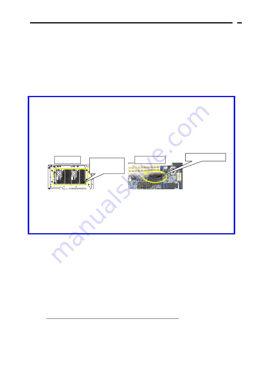
If the server was installed the redundant power supply, please check the cable is installed to the
I2C_Bus connector(PSMI1) on the MB correctly. If the cable is not connect, please plug off the AC
cords and connect the cable of the redundant power supply with P4 connector correctly.
3). T
his setup procedure need to boot the server from CD-ROM.
The boot device order may have been changed depending on the machine's operating environment.
In this case, the boot device order must be changed temporarily to boot from CD-ROM on BIOS
SETUP.
After completing SDR/PIA setup, please restore the boot device order to the customer’s setting.
[Operating Procedure]
①
Start the server.
②
Insert the attached [SDR/PIA UPDATE TOOL ( 243-420216-002 ) ] CD-ROM in the optical disk drive of
the server.
③
After the CD-ROM is inserted, reset the server by pressing <Ctrl> + <Alt> + <Del> keys or turning off/on
the power to reboot the server.
④
The system starts from the CD-ROM and the SDR/PIA setup starts automatically.
1to 2 minutes is required to complete the setup.
Be sure not to turn off the power during the setup.
Redundant
power supply
I
2
C_Bus connecter
Mother Board
Rear View
Содержание N8154-24
Страница 17: ...5 9 本体装置の底面にあるネジ 2 本を外します 10 ディスクケージフレーム側面からネジを 2 本外します 11 ディスクケージフレームをL字型の溝に沿って 持ち上げて移動させます ...
Страница 19: ...7 15 手順 7 で外した皿ネジ 2 本で本体シャーシ前面を固定します 16 本体装置の前面の下側スロットに 2 5 型ディスクケージを取り付け 本製品に添付されているネジ 4 本で固定します ...
Страница 21: ...9 21 ケーブルを温度センサーボードに接続します 22 ケーブルを傷つけないように注意しながら温度センサーボードを取り付けたブラケットを取り付け ます 23 本製品に添付のネジ 3 本で固定します ...
Страница 34: ...22 ...
Страница 58: ...13 Make sure that the jumper settings are as shown below ...


