47
Install Cabinets for Bottom-Row on Power Bar
6.3.2
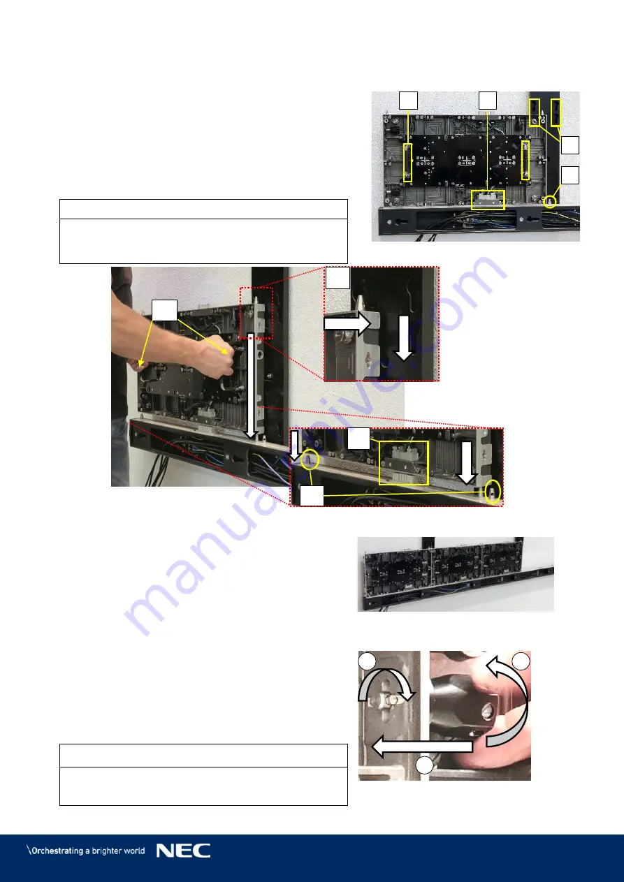
Use the grip handles on the cabinet (Figure 49,
Step 1)
A) to bring it into position at left corner on the
Power bar.
Align together the Cabinet hanger pins with the
Step 2)
Mounting bar sockets (B) and the Corner
alignment pins on the Power bar (C).
Lower the cabinet onto the Network-PS socket
(D), gently pressing it until it sits firmly.
Notice
Place the cabinet carefully and straight on top of the
Network-PS socket. Otherwise, the data connection
may be pushed out and not function properly.
Figure 49: Installing the First Cabinet
Install further cabinets until the first row is
Step 3)
complete.
Figure 50: Installing Additional
Cabinets – First Row
Connect each cabinet to its adjacent cabinets
Step 4)
with the Cabinet interlocks.
Push in the lock bolt.
a)
Turn the lock bolt 90° to lock.
b)
Fix the black nut to secure the lock finger
c)
tight.
Figure 51: Locking Two Modules
Notice
Do not tighten the Cabinet interlocks too much.
Otherwise the cabinets cannot be aligned later on.
C
A
B
D
b
a
c
A
C
B
D
Содержание LED-FA025i2-220
Страница 61: ...61 Figure 78 Screen Settings for 8 8 Controller...
Страница 91: ...91 Part Name AC terminal Hub For 0 9 mm only CAT cable Mask For 1 5 1 9 2 5 3 8 mm only...
Страница 96: ...96 LED FA015i2 137 Data Connections 15 1 3 LED FA015i2 137 Power Connections 15 1 4...
Страница 97: ...97 LED FA019i2 165 Data Connections 15 1 5 LED FA019i2 165 Power Connections 15 1 6...
Страница 99: ...99 LED FA012i2 220 Data Connections 15 1 9 LED FA012i2 220 Power Connections 15 1 10...


