background image


30 

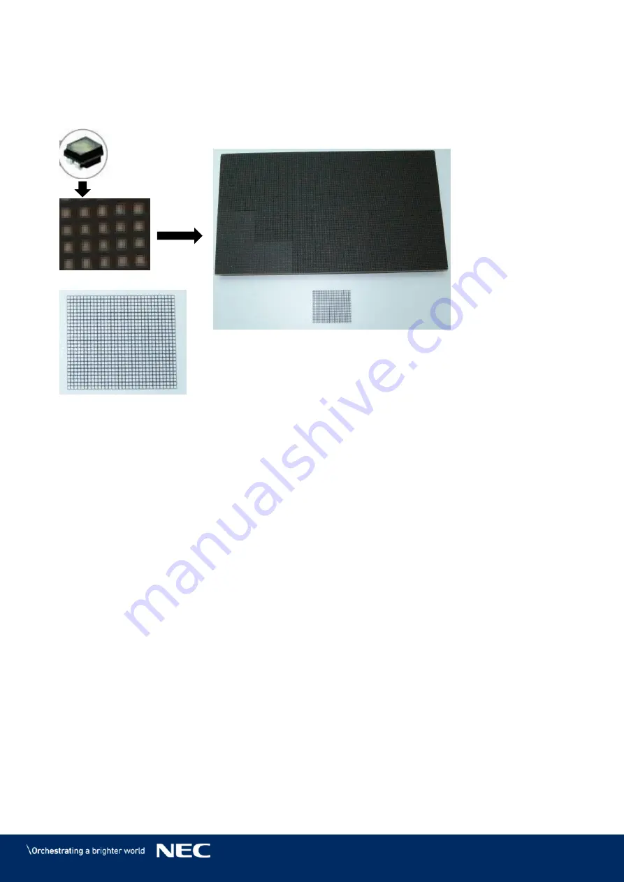
Black Masks 

The Black masks cover and protect the electronic surface between the LEDs of the Pixel card PCB. 
In combination with our high-end LED-chips (A), the mask (B) is necessary to get the best 
black-values, which result in a high contrast ratio of the screen. 


Figure 25: LED Chip and Usage of the Black Masks 


Содержание LED-FA025i2-220

Страница 1: ...ne Pitch LED Video Display Indoor USER GUIDE For models LED FA012i2 110 LED FA019i2 110 LED FA015i2 137 LED FA019i2 165 LED FA012i2 220 LED FA025i2 220 LED FA038i2 220 LED FA031i2 LED FA012i2 SB LED F...

Страница 2: ...for LED FA015i2 137 5 5 Modules 18 3 3 2 Frameset for LED FA019i2 165 6 6 Modules 18 3 3 3 Frameset for LED FA012i2 220 and LED FA025i2 220 3 3 4 LED FA038i2 220 8 8 Modules 19 3 4 Specification 20 3...

Страница 3: ...Power Bar 50 Connect Data Cables to the Power Bar 50 6 4 1 Connect Power Cables to the Power Bar 51 6 4 2 Check the Power Supply and Data Connection of the Modules 51 6 4 3 6 5 Install Overframes and...

Страница 4: ...Cable Plans 95 LED FA012i2 110 LED FA019i2 110 Data Connections 95 15 1 1 LED FA012i2 110 LED FA019i2 110 Power Connections 95 15 1 2 LED FA015i2 137 Data Connections 96 15 1 3 LED FA015i2 137 Power C...

Страница 5: ...Redundant Receiving Cards 32 Figure 29 Behind Hub Board Redundant Power Supply with Wired PDU with PDU Shielding 32 Figure 30 Pin Connection from PDU to Redundant PSUs 33 Figure 31 Signal Lights on t...

Страница 6: ...fter loading Module Calibration Data 64 Figure 84 Flash Module after saving Module Calibration Data 64 Figure 85 Calibration is disabled 65 Figure 86 Calibration is enabled 65 Figure 87 Saving calibra...

Страница 7: ...Pixel Card 86 Figure 118 Foam Forms for Pixel Cards 87 Figure 119 Cabinet without Pixel Cards 87 Figure 120 Screws on Hub Board 87 Figure 121 Removal of Hub Board 87 Figure 122 Replacing the Receiving...

Страница 8: ...g bar Installation requirements 41 Table 7 Number and Position for Anchor Points 43 Table 8 Power Bar Installation Requirements 45 Table 9 Cabinet Installation Requirements 46 Table 10 Cable Connectio...

Страница 9: ...e severity of a potential hazard WARNING A warning for a potentially hazardous situation that can result in death personal injury or property damage if not adhered to Caution A recommendation for a po...

Страница 10: ...respectively authorized personal may carry out repairs service and maintenance work on the system A case of service occurs as soon as one component is damaged in any way is not fully functional any m...

Страница 11: ...les regularly Replace damaged cables immediately they are not user serviceable Caution Risk of fire and product damage by aggressive substances Keep the system away from aggressive substances inflamma...

Страница 12: ...entilation holes Keep them free at all times To protect the power cable against overload maximum 10 cabinets shall be wired in a row at 100 V AC or 20 modules at 240 V AC The total load must not excee...

Страница 13: ...transition ramps cable channels Protect the cable against kinks and sharp edges Notice Use a TN S power distribution system with a separate neutral and grounding conductor Due to voltage differences i...

Страница 14: ...may cause harmful interference to radio communications Operation of this equipment in a residential area is likely to cause harmful interference in which case the user will be required to correct the...

Страница 15: ...g card the other Receiving card provides the picture 3 1 Scope of Delivery FA Series Bundle LED FA012i2 110 LED FA019i2 110 LED FA015i2 137 LED FA019i2 165 LED FA012i2 220 LED FA025i2 220 LED FA038i2...

Страница 16: ...er plate 1 1 1 1 5 Power bar screw M8 20 Hexagon socket head screw 8 10 12 24 6 Power bar 1 1 1 2 Bottom frame connecting part 1 7 Screw for corner frame bottom M6 12 Hexagon socket head screw 2 2 2 2...

Страница 17: ...7 LED FA019i2 165 LED FA012i2 220 LED FA025i2 220 LED FA038i2 220 Display size inch cm 110 279 137 348 165 419 220 559 Dimensions incl frame W H 2472 1488 mm 3080 1830 mm 3688 2172 mm 4904 2856 mm Wei...

Страница 18: ...18 Frameset for LED FA015i2 137 5 5 Modules 3 3 2 Figure 2 Frameset for LED FA015i2 137 5 5 Modules Frameset for LED FA019i2 165 6 6 Modules 3 3 3 Figure 3 Frameset for LED FA019i2 165 6 6 Modules...

Страница 19: ...19 Frameset for LED FA012i2 220 and LED FA025i2 220 LED FA038i2 220 8 8 3 3 4 Modules Figure 4 Frameset for LED FA012i2 220 and LED FA025i2 220 LED FA038i2 220 8 8 Modules...

Страница 20: ...Rear IP20 Service availability Front service Displays Power max average 600 W m 125 W module 315 W m 66 W module 600 W m 125 W module 280 W m 57 W module Viewing angle HOR L R 85 85 VER U L 85 85 Bri...

Страница 21: ...ear IP20 Service availability Front service Displays Power max average 580 W m 120 W module 230 W m 47 W module Viewing angle HOR L R 80 80 VER U L 70 70 Brightness 1200 cd m Brightness tolerance 10 C...

Страница 22: ...vailability Front service Displays Power max average 600 W m 125 W module 280 W m 57 W module 720 W m 150 W module 380 W m 80 W module Viewing angle HOR L R 70 70 VER U L 70 70 Brightness 400 cd m 600...

Страница 23: ...ets for Bundles Power bar 3 5 7 Power Bar Figure 5 LED Wall Components Module 3 5 1 The module consists of eight Pixel cards and a cabinet For information on Type A and B modules cabinets see 3 5 2 Ca...

Страница 24: ...e A Cabinets have two connectors for data and power Network and power supply socket one on the top and one at bottom of the case see Figure 11 Type B Cabinets have only one connector for data and powe...

Страница 25: ...meters Figure 12 Corner Alignment Pins 3 5 2 2 Cabinet Interlocks The Cabinet interlocks guarantee quick installation and easy maintenance Each cabinet has two sets of Cabinet interlocks two sets of b...

Страница 26: ...ft and right from the hub board These provide for easy handling during installation and maintenance in the open position and conveniently collapse into the cabinet when not in use Figure 14 Figure 15...

Страница 27: ...Figure 17 and secured on the inside of the cabinet Figure 18 H If used as fixed installation optional matched connectors can be adopted to connect the Corner alignment pin and support frame Figure 16...

Страница 28: ...is connected to Ethernet ports Figure 19 B on the Hub board D and to the Power distribution unit PDU wiring C The sockets wire to the PDU Figure 21 E and ground F on the cabinet The PDU in turn conne...

Страница 29: ...connections to the Hub board or Cabinet Three types of interfaces help to secure Pixel cards within the cabinet Click pin interfaces D counter part to the corner click pins on Pixel card ensure the r...

Страница 30: ...ctronic surface between the LEDs of the Pixel card PCB In combination with our high end LED chips A the mask B is necessary to get the best black values which result in a high contrast ratio of the sc...

Страница 31: ...er supply socket 16 screw connections to cabinet C To secure the Hub board in the cabinet Figure 26 Hub Board Front The backside of the Hub board has several interfaces for data and power distribution...

Страница 32: ...ent reserve In a case of failure of one or the other unit the functional PSU can be delivered in full power from the remaining unit In rare cases where both PSUs are defective the Power supply units o...

Страница 33: ...lights are on the back of the module Figure 31 They indicate the status of the module The three lights are red green and blue Figure 31 Signal Lights on the Back of the Module The Signal lights are fi...

Страница 34: ...and connects to each row of modules via the Network and power supply socket The Power bar also serves as cable conduit The cables for power supply and data transmission run inside the Power bar from...

Страница 35: ...e Figure 34 are reference values Make sure the room is well ventilated so that hot air generated by the product does not accumulate Also make sure the room temperature is within the range of the envir...

Страница 36: ...ach particular project Depending on the structural design and environmental temperature it may be necessary to add an external cooling To integrate the ideal energy efficient air conditioner for the L...

Страница 37: ...ore information see 15 1 Cable Plans External NovaStar Controller to PC Signal cables to connect the NovaStar Controller and a PC are included Refer to Table 4 to choose the correct signal cable for t...

Страница 38: ...38 5 PREPARE FOR USE 5 1 Cabinet Packaging One cabinet box contains the following Foam cover 1 PE bag 2 Cabinet 3 Foam container 4 Cardboard box 5 Figure 37 Package Order of Module Box 1 2 1 3 4 5...

Страница 39: ...rds Packaging One Pixel card box contains the following Foam cover 6 Antistatic bag 7 Pixel card 8 Foam container 9 Cardboard box 10 PE bag 11 Figure 38 Package Order of Pixel Card Box 6 11 11 9 6 7 1...

Страница 40: ...efore starting the installation Ensure that the installation site is suitable for the cable routing plan If necessary mark important points of the plan on the wall used for the installation Regarding...

Страница 41: ...pending on mounting surface wall material condition Mounting material screws dowels etc depending on overall weight of chosen screen system mounting surface wall material condition Measurement tools e...

Страница 42: ...oints to drill out See markings in figures below or the dimensions in Table 7 Use the spirit level to check the vertical alignment of the marks before drilling Figure 39 Positions for Anchor Points 4...

Страница 43: ...e center 1216 mm Others 608 equally Distance Vertically 1026 mm 684 mm equally Distance top row middle row 1026 mm Distance middle row bottom row 684 mm Distance Bottom row 342 mm others 684 mm equall...

Страница 44: ...of the frame elements using the Alignment bar Step 2 Use the spirit level together with the Alignment bar to check the evenness Figure 43 Step 3 and Figure 44 If necessary adjust the positions accord...

Страница 45: ...ss 6 2 1 Use the Alignment bar and spirit level in combination to check the evenness between Step 1 the vertical Mounting bars If necessary adjust top and bottom supports accordingly Step 2 Bring Powe...

Страница 46: ...Requirements No of People 2 Prerequisites Frameset securely installed Power bar securely installed Tools Screwdriver Allen key Equipment Cabinets Cabinet hanger pins Adjustment plate Figure 47 Wall M...

Страница 47: ...nd straight on top of the Network PS socket Otherwise the data connection may be pushed out and not function properly Figure 49 Installing the First Cabinet Install further cabinets until the first ro...

Страница 48: ...Vertical Alignment of Cabinets Secure Cabinet to Power Bar 6 3 3 Connect the cabinets of the first row to the Power bar For this screw a M8 16 screw Step 1 in the opening for the Cabinet interlocks a...

Страница 49: ...with the Cabinet interlocks Push in the lock bolt a Turn the lock bolt 90 to lock b Fix the black nut to secure the lock c finger tight Figure 55 Locking Two Modules Notice Do not tighten the Cabinet...

Страница 50: ...l to NovaStar Controller Cat cable FTP Cat5e Figure 57 Connections in Power Bar A External power input C1 Ethernet port main data B Terminal in Power bar C2 Ethernet port backup data C Network and sup...

Страница 51: ...ion Risk of electric shock and product damage Ensure the Power bar and the whole LED Wall are properly grounded before putting it into use Check the Power Supply and Data Connection of the Modules 6 4...

Страница 52: ...rame Tools Screwdriver Allen key Service tool Equipment Overframes Corner frame bottom left right Overframe left right LED Wall Overframe top Corner frame top left right Power bar cover Attach the Cor...

Страница 53: ...r frame bottom left right Figure 61 Installing Overframes left right Attach the Overframes left right to the LED Wall by screwing the M8 16 screws C Step 8 through the Cabinet interlock anchors into t...

Страница 54: ...lts flaking skin and or other forms of human excretory secretions The LED modules and their electrical components are sensitive to biological agents and exposure to such risks degradation of materials...

Страница 55: ...re that the surface of the LED Wall is even Step 3 If a Pixel card sticks out minimize the Step 4 protrusion with the level screws A in the cabinet Remove the Pixel card with the Service a tool Figure...

Страница 56: ...troller is no product of NEC DISPLAY SOLUTIONS For detailed information on the NovaStar Controller see the respective manual for NovaStar Controller MCTRL660 PRO Download the current version at https...

Страница 57: ...oftware NovaLCT Step 1 Click the User U register and select Advanced Synchronous System User Step 2 Login A see Figure 69 Figure 69 Advanced User Login Enter the password into the Password field The d...

Страница 58: ...Result Screen Configuration opens The pop up opens see Figure 72 Figure 72 Pop Up Configurating the Screen Connection Click the Next button The screen refreshes see Figure 73 Step 5 Figure 73 Start Sc...

Страница 59: ...elivered USB flash drive and click Open button confirm Step 8 the loading message with OK button Result The scr file will be loaded Click the Send to HW button to save the configuration Confirm the up...

Страница 60: ...76 and Figure 77 Close the software by clicking X button or the Close button Step 10 Settings for bundles 4 4 5 5 and 6 6 Figure 76 Screen Settings for 4 4 Controller LED FA012i2 110 and LED FA019i2 1...

Страница 61: ...61 Figure 78 Screen Settings for 8 8 Controller...

Страница 62: ...ards Login as Advanced User Step 1 Click the Calibration button The screen refreshes automatically see Figure 79 and Step 2 Figure 80 Figure 79 Start Screen Starting Calibration Figure 80 Start Screen...

Страница 63: ...Coefficients tab see Figure 81 Step 4 Figure 81 Screen Calibration Register Manage Coefficients Click on Module Flash Step 5 Result The module flash options will appear see Figure 82 Figure 82 Starti...

Страница 64: ...message that the data has been successfully stored to the Receiving cards will appear see Figure 84 Result The screen with the exchanged Pixel cards should look calibrated now Figure 84 Flash Module...

Страница 65: ...alibration setting Disable Calibration is chosen switch to Chroma Calibration to Step 11 enable calibration and click on the Save button see Figure 86 Result While switching you will already see calib...

Страница 66: ...abase Figure 87 Step 1 Figure 87 Saving calibration data Select Saved to a New Database Figure 88 Step 2 Select Screen Database Figure 88 Create the calibration data file Step 3 Click Create Figure 88...

Страница 67: ...7 Specify a file name and a save location and then click Save Figure 89 Step 4 Figure 89 Specifying the file name and the save location Click Next Figure 90 Step 5 Figure 90 End of the creation proces...

Страница 68: ...the transfer finished successfully is displayed click OK Click Return Figure 91 Figure 91 Transferring the calibration data Under Current Screen select the screen for calibration Step 7 Enable calibra...

Страница 69: ...tion data file for backup from the save location Step 10 specified in step 4 Figure 93 Click Next Figure 93 Figure 93 Selecting the calibration data file for backup Select Screen and then click Next F...

Страница 70: ...ansfer begins The transfer takes approximately 1 hour and 10 minutes When the screen indicating that the transfer finished successfully is displayed click OK Click Save Figure 95 Click Finish Figure 9...

Страница 71: ...adjustment automatic brightness and manual brightness Multi function Card Open the page for Multi function card configuration Multiple screen Management Open the page for combined display configuratio...

Страница 72: ...en control functions which include Black Out Freeze and Normal Besides self test options are also provided Monitoring View the monitoring results or set the monitoring parameters LED Error Detection D...

Страница 73: ...alculator Open the Microsoft Windows calculator External Program Add an external program DHCP Service Obtain the IP address assigned by the server User Advanced User Login Log in the synchronous syste...

Страница 74: ...nous System User Login A Step 2 see Figure 97 Figure 97 Advanced User Login Enter the password into the Password field The default password is admin Step 3 Click the Login button to confirm the entry...

Страница 75: ...Receiving Card Check the wiring of the Receiving card and the Power supplies Temperature Check the temperature of each module and the Operating status of each individual Power supply solution Monitori...

Страница 76: ...d to log in to NovaLCT as Advanced Users to configure the Monitoring parameters Start the software NovaLCT Step 1 Click the User U menu Step 2 Enter the password into the Password field The default pa...

Страница 77: ...77 Figure 103 Start Screen Monitoring for Advanced Users Click the Monitoring button The monitor interface will open automatically see Figure Step 5 104 Figure 104 Start Screen with Configuration Mode...

Страница 78: ...r the marked parameters see Figure 105 Click the Save button Step 7 Result The parameters are activated in the Monitoring interface see Figure 106 By moving the mouse over the screen mapping a pop up...

Страница 79: ...es The color codes are defined in the interface itself Click the Monitoring button to open the monitoring interface see Figure 107 Step 1 Result The Monitoring interface will open By default the Monit...

Страница 80: ...he Monitoring button to open the Monitoring interface see Figure 109 Step 1 Result The Monitoring interface will open By default the Monitoring view for the Receiving cards is opened see Figure 110 Fi...

Страница 81: ...ch individual power supply solution Errors will be shown in colored surfaces The color codes are defined in the interface itself Click the Monitoring button to open the monitoring interface see Figure...

Страница 82: ...3 Start Screen Monitoring Receiving Cards and Power Supplies Click the Temperature button to switch to the Monitoring view for the temperature Step 2 see Figure 114 Figure 114 Start Screen Monitoring...

Страница 83: ...ation environment Required tools example Soft brush animal hair brush to prevent static electricity Soft cloth that does not generate static electricity Air blower compressor 1 Cleaning method Turn th...

Страница 84: ...Pixel Cards with a damp cloth Notice Clean the components of the LED Wall very carefully to avoid damaging the surfaces Do not alter the cleaning procedure above otherwise pixels or Pixel cards can be...

Страница 85: ...the Service tool to remove the Pixel cards in a safe and easy way The Service tool comes with a battery and charger for wireless usage Ensure the Service tool is charged properly before using it Usag...

Страница 86: ...plastic bag for the Pixel cards Heat conducting paste for servicing the power supply Change the Pixel Cards 10 5 1 The Front Service takes only 10 seconds to exchange a pixel module This convenience i...

Страница 87: ...the Hub Board 10 5 2 For servicing the Hub board you need to remove the Pixel cards first see 10 5 1 Disconnect the Ethernet connections A Step 1 from the Hub board Remove the 16 screws B which conne...

Страница 88: ...the Receiving card Step 2 To replace the Receiving card follow the Step 3 instructions in reverse order Figure 122 Replacing the Receiving Card Change the Power Supply System 10 5 4 For servicing the...

Страница 89: ...replaced PDU follow the steps in reverse order Step 6 Replace the Power Supply Unit To replace the PSU remove the Power distribution unit PDU first See above for instructions Remove the two screws G S...

Страница 90: ...RE PARTS Part Name Pixel Card Pixel Card For 2 5 mm only Receiving card A8S Receiving card A10S Plus For 0 9 mm only Power supply Power supply For 0 9 mm only Data hub Data hub For 0 9 mm only AC term...

Страница 91: ...91 Part Name AC terminal Hub For 0 9 mm only CAT cable Mask For 1 5 1 9 2 5 3 8 mm only...

Страница 92: ...he screen saver is activated No signal input Check the green LED of the Receiving card is flickering regularly or not fast flickering means no signal 1 Check if the cable connector assembly is stable...

Страница 93: ...ors and electrical accessories such as signal cables or power cords When you dispose of such products please follow the guidance of your local authority or ask the shop where you purchased the product...

Страница 94: ...surements weights and properties are not guaranteed The manufacturer reserves the right to make product alterations within legal provisions as well as changes to improve product quality Sharp NEC DISP...

Страница 95: ...95 15 APPENDIX 15 1 Cable Plans LED FA012i2 110 LED FA019i2 110 Data Connections 15 1 1 LED FA012i2 110 LED FA019i2 110 Power Connections 15 1 2...

Страница 96: ...96 LED FA015i2 137 Data Connections 15 1 3 LED FA015i2 137 Power Connections 15 1 4...

Страница 97: ...97 LED FA019i2 165 Data Connections 15 1 5 LED FA019i2 165 Power Connections 15 1 6...

Страница 98: ...98 LED FA025i2 220 LED FA038i2 220 Data Connections 15 1 7 LED FA025i2 220 LED FA038i2 220 Power Connections 15 1 8...

Страница 99: ...99 LED FA012i2 220 Data Connections 15 1 9 LED FA012i2 220 Power Connections 15 1 10...

Страница 100: ...ole cabinet Connect Power cable LAN cable to use the following components Option parts LED FAFE2 BHCK Connection method Attach the feed sleeve to the cabinet Step 1 Backside hole Back view Backside ho...

Страница 101: ...101 Insert the cables Step 2 Attach the buckle by screw Step 3 Through the fastening tie lap Step 4 Power cable LAN cable...

Страница 102: ...tie lap Step 5 Connect the Power cable inside outside like bellows Step 6 WAGO 221 is just example to connect the cable Please arrange on your side Front view Power cable LAN cable WAGO 221 Inside po...

Страница 103: ...D FA009i2 FA009i2 165 6x6 0 95mm 3840 x 2160 by client LED Controller Main 1 LED Controller Main 2 LED Controller Main 1 LED Controller Main 2 by client shielded CAT6a max length 60m RJ45 connectors o...

Страница 104: ...6 0 95mm 3840 x 2160 FA009i2 165 6x6 0 95mm 3840 x 2160 200V 240V Max 16A 200V 240V Max 16A 200V 240V Max 16A 100V 120V Max 16A 100V 120V Max 16A 100V 120V Max 16A 100V 120V Max 16A 100V 120V Max 16A...

Страница 105: ...105 FA009i2 165 6x6 0 95mm 3840 x 2160 terminal block terminal block terminal block A1 Backside hole cabinet C1 Type A B1 Type B...

Отзывы: