i-Series Gateway
Page 8
G-6000G-SKE, Rev AA
Power-Up
1. Once the VT-100 program is set up, plug the unit into an AC outlet. The device begins a series of self-
diagnostic tests, which are displayed as a series of LED flashes.
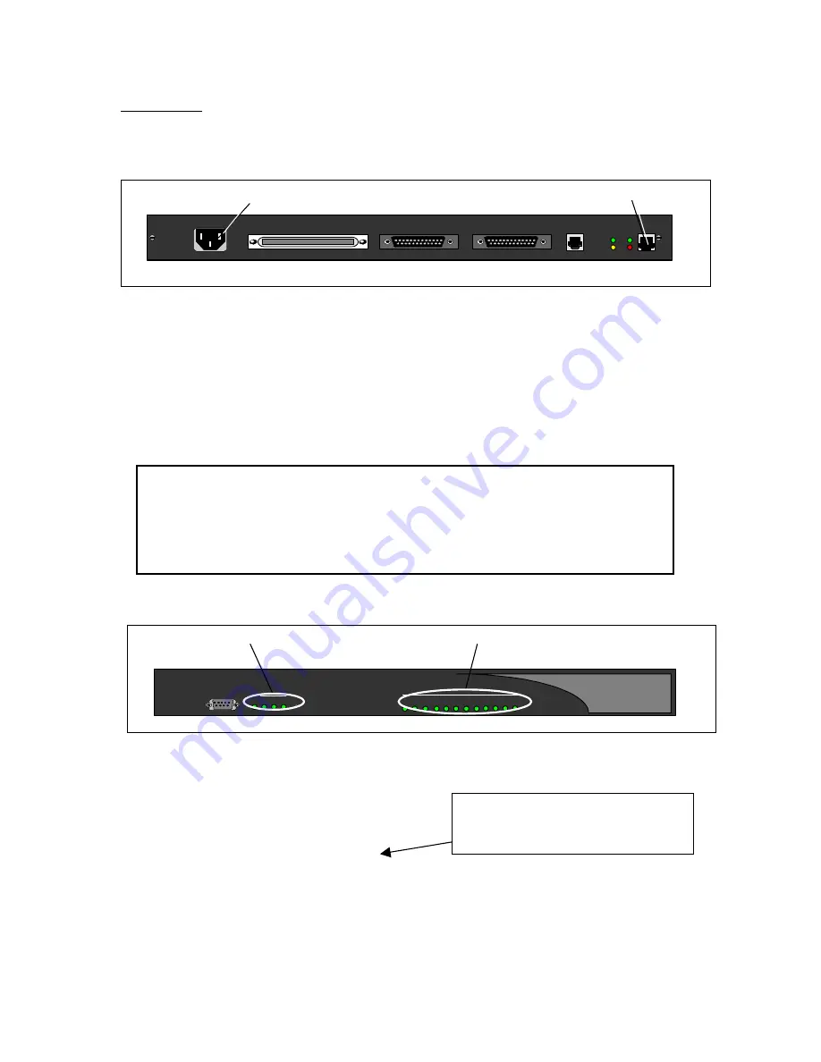
Back of Unit (For a VOIP connection, see notes below.)
LAN Notes:
The state for the LEDs labeled XMT (Transmit), RCV (Receive), and CLN (Collision) varies depending
on the status of the network. These LEDs are not critical for verifying the "Power-up Sequence".
LNK LED should be solid green.
If you connect an i-Series Gateway to an IP network, the unit requires an assigned IP address.
The Ethernet port on the Gateway operates only on 10-megabit Ethernet networks. It does not support
100 megabits.
2. Once the power-up sequence is finished, the state of the following LEDs should be Green.
LED States:
PWR: Solid Green
WAN1: Solid Green (Ready) if a synchronous device is connected to WAN 1.
Solid Orange (Ready) if an asynchronous ISDN TA is connected and accepting
commands (but there is no link up- in Call Suspend mode or have not dialed it yet).
Port LEDs: Solid Green if connected properly to PBX.
IMPORTANT:
If any of the LEDs DO NOT power as explained, refer to the System
Administrator’s Guide for troubleshooting information.
Front of Unit
On initial power-up (or before the config file has been changed) the Management Interface (MI)
displays the following prompt.
Press “Enter” to start the i-Series Gateway shell…..
Do you want to run the “Setup Wizard”
If you type “Yes”, the wizard asks a series of configuration questions. (See page 16.)
If you type “NO”, you enter the main MI.
3. Go
to
Basic Configuration on the next page.
AC Power LAN Connection
LNK
CLN
ANALOG LAN
0
TELEPHONY INTERFACE
WAN 1
WAN 2
XMT LNK
RCV CLN
100-240 V ~ 0.8A 50-60 HZ
PWR and WAN 1 (Connected) Ports
LN K
C LN
3
1
2
8 9 10 11 12
7
6
5
4
Port Status
PW R 1
3
2
C onsole
W AN
R eset
If the i-Series Gateway is powered up
prior to opening the terminal program,
this message will not appear.


