


4. Names and Functions of Parts
Express5800/T120h User’s Guide
40
Chapter 1 General Description
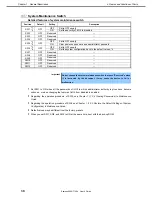
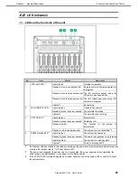
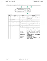
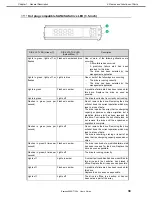
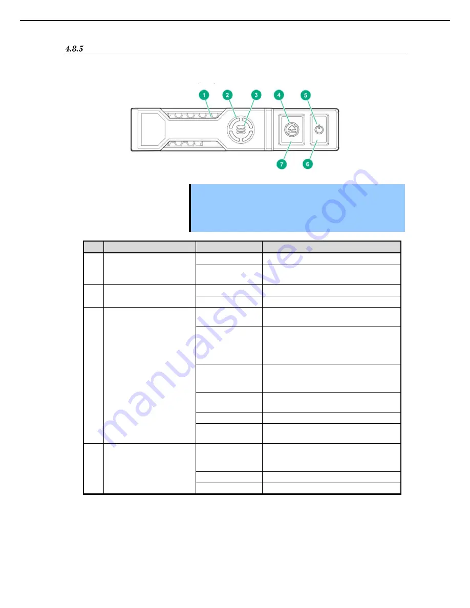
NVMe drive LED
NVMe SSD is a PCIe bus device. Devices connected to the PCIe bus cannot be removed until the signals of
device and bus and traffic flow are completely terminated.
Important Do not remove the NVMe drive from the drive bay if the removal-prohibiting
LED is blinking. The blinking of the removal-prohibiting LED indicates that
the device is still in use. Removing the NVMe drive before the device signals
and traffic flow are completely terminated may result in data loss.
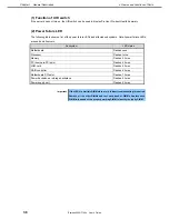
No.
Item
Status
Description
1
Position Check LED
Lights in blue
The drive is identified by the host application
Flashes in blue
Drive carrier firmware is being updated or
requires an update
2
DISK ACT LED
Rotates in green
Drive is working
Lights off
Drive is not working
3
DISK STATUS LED
Lights in green
The drive is a member of one or more logical
drives.
Flashes in green
The drive is being rebuilt; or the drive is
transferring RAID, transferring stripe size,
increasing capacity, or increasing the logical
drive; or the drive is being erased.
Flashes in
amber/green
The drive is a member of one or more logical
drives, and it is estimated that there is a
problem with the drive.
Flashes amber
The drive is not configured, and it is estimated
that there is a problem with the drive.
Lights in green
There is a problem with the drive.
Lights off
There is no organization in the drive by the
RAID controller.
4
Removal Prohibition LED
Lights in white
Do not remove the drive.
Remove the drive once it is separate from the
PCIe bus.
Flashes in white
The drive can be removed.
Lights off
The drive has been removed.


