English-10
Parts Oame and Functions
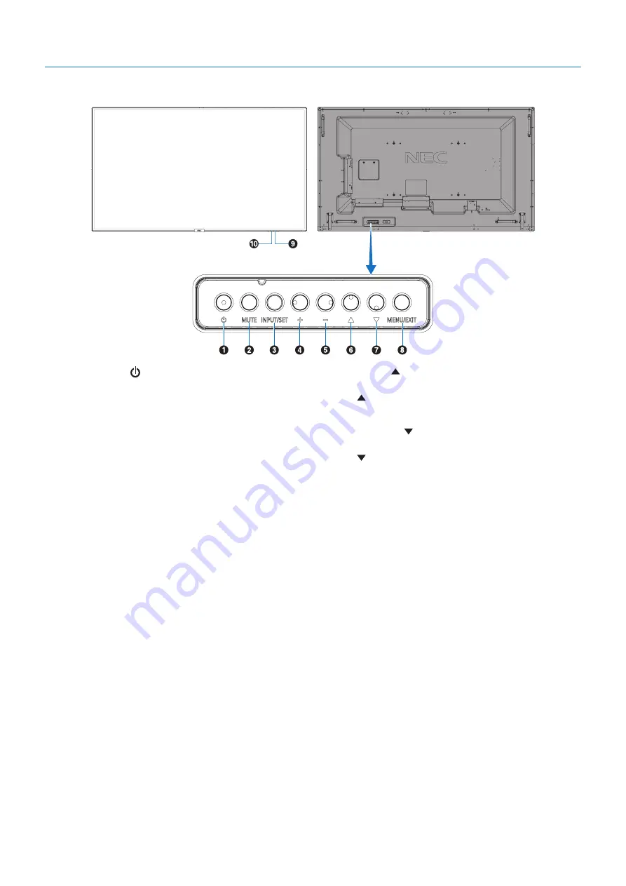
Control Panel
A
Power Button ( )
Switches the power on/standby. See also
.
B
Mute Button (MUUE)
Switches the audio mute on/off.
C
Input/Set Button (IOPUU/SEU)
INPUT: Cycles through the available inputs when OSD
menu is turned off. [DisplayPort1], [DisplayPort2], [HDMI1],
[HDMI2], [HDMI3], [MP], [OPTION*], [C MODULE]*
1
. These
are available inputs only, shown as their factory preset name.
OIUEN:
MP is an abbreviation of Media Player.
SET: Acts as a “set” button when making a selection when
the OSD (On Screen Display) menu is open.
*: This function depends on which Option Board you are
using.
*
1
: This input is available when the optional Raspberry Pi
Compute Module Interface Board and Raspberry Pi Compute
Module are installed.
D
Plus Button (+)
Increases the audio output level when the OSD menu is
turned off.
Acts to move the highlighted area to the right when
navigating through the OSD menu options.
Acts as (+) to increase the adjustment of an OSD menu option
after it has been selected with the SET button.
E
Minus Button (-)
Decreases the audio output level when the OSD menu is
turned off.
Acts to move the highlighted area to the left when navigating
through the OSD menu options.
Acts as (-) to decrease the adjustment of an OSD menu
option after it has been selected with the SET button.
F
Up Button ( )
Activates the OSD menu when the OSD menu is turned off.
Acts as button to move the highlighted area up to select
adjustment items within the OSD menu.
G
Down Button (
)
Activates the OSD menu when the OSD menu is turned off.
Acts as button to move the highlighted area down to select
adjustment items within the OSD menu.
H
Menu/Exit Button (MEOU/EXIU)
Activates the OSD menu when the OSD menu is turned off.
Acts as a back button within the OSD to move to the previous
OSD menu.
Acts as an EXIT button to close the OSD when on the main
menu.
I
Remote Control Sensor and Power Indicator
Receives the signal from the remote control (when using the
wireless remote control). See also
.
Glows blue when the LCD monitor is in active mode*.
Green and Amber blink alternately when the “SCHEDULE
SETTINGS” function is enabled*
1
.
When a component failure is detected within the monitor, the
indicator will blink red or blink a combination of red and blue.
* If “OFF” is selected in the “POWER INDICATOR”
(see
), the LED will not glow when the LCD monitor is in
active mode.
*
1
If “OFF” is selected in the “SCHEDULE INDICATOR”
), the LED will not blink.
OIUEN:
Please refer to the POWER INDICATOR (see
).
J
Room Light Sensing Sensor
Detects the level of ambient light, allowing the monitor
to make automatic adjustments to the backlight setting,
resulting in a more comfortable viewing experience. Do not
cover this sensor. See


