Section 2: PCB Installation and Startup
2-48
Section 2: PCB Installation and Startup
Aspila EX Hardware Man-
PCB STARTUP
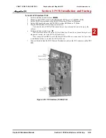
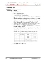
Initial PCB Installation
When first installing the system:
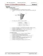
1. Ensure the cabinets are powered off.
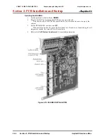
2. Insert the NTCPU PCB into the CPU slot.
3. Insert an ESIU PCB in slot 1 of the Main Cabinet.
PCBs for slots 2-16 are not installed at this time.
4. Plug in all system telephones. A display telephone should be plugged into port 001 (extension
200).
5.
When starting the system for the first time,
hold the LOAD button on the NTCPU and turn
the AC Power Panel switch to ON. After approximately 3 seconds, release the LOAD button.
This performs a cold start on the Aspila EX system to make sure you’re starting with a
defaulted system.
When powering up any other time,
simply turn the AC Power Panel switch to ON.
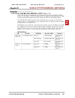
Refer to
Switch Settings and LED Indications
on page 2-9 for NTCPU LED status.
6. Wait about three minutes for the system to boot. The telephone display at extension 200 will
show the Time/Date and extension number when the boot sequence completes.
7. Set the run/block switch to run
UP
on the ESIU in slot 1.
8. After setting the run/block switch
DOWN
for all SLIU/ESIU PCBs, insert SLIU/ESIU PCBs
in the Main Cabinet in sequential order.
The order in which SLIU and ESIU PCBs are physically inserted determines the num-
bering plan.
The installer must install extension PCBs in order (i.e.; slot 1 first, slot 2 next,
slot 3 next, etc.) for a sequential numbering plan.
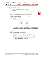
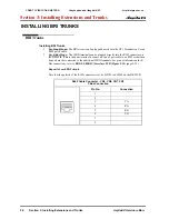
For example, with a 16ESIU in slot #1 (ext. 200-215), when 3 more 16ESIU PCBs are
installed in the following order, the numbering plan below would apply:
9. Set the run/block switch
UP
on each PCB.
Order of
Install
PCB Slot #
PCB
Extension
Numbers
1
1
16ESIU
200-215
2
2
16ESIU
216-231
3
4
8SLIU
(no daughter board)
232-239
4
3
8ESIU
240-247
CÔNG TY VIỄN THÔNG VIỆT PRO
Chuyên phân phối tổng đài NEC
http://vietpro.com.vn


