Section 4: Optional Equipment
4-2
Section 4: Optional Equipment
Aspila EX Hardware
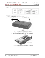
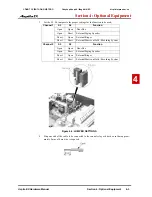
LED Indications
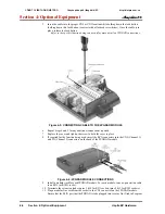
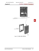
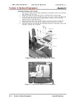
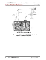
Setting Up 2PGDAD Module Connections
1. Remove the screw from the front of the 2PGDAD module.
Figure 4-2: REMOVE COVER FROM 2PGDAD MODULE
2. Using a screwdriver, break out the plastic piece covering the cable hole.
Figure 4-3: REMOVE PLASTIC COVER FROM CABLE HOLE
LED
Indication
Note
LED 1
Green LED when
CH1 in use.
Flashing green LED indicates dipswitch setting
and programming for CH1 is conflicting.
LED 2
Green LED when
CH2 in use.
Flashing green LED indicates dipswitch setting
and programming for CH2 is conflicting.
CÔNG TY VIỄN THÔNG VIỆT PRO
Chuyên phân phối tổng đài NEC
http://vietpro.com.vn


