Section 2: PCB Installation and Startup
Aspila EX Hardware Manual
Section 2: PCB Installation and Startup
2-29
2
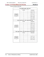
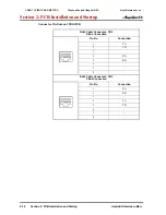
Connector Pin-Outs on 4TLIU PCB
RJ61 Cable Connector - 2-Wire E&M, CN100 - CN400
Pin No.
Connection
Description
1
SB
Ground wire for control
2
M
Control signal to trunk
3
-
4
R
Voice signal both ways
5
T
Voice signal both ways
6
-
7
E
Control signal from trunk
8
SG
Ground wire for control
RJ61 Cable Connector - 4-Wire E&M, CN100 - CN400
Pin No.
Connection
Description
1
SB
Ground wire for control
2
M
Control signal to trunk
3
R
Voice signal to trunk
4
R1
Voice signal from trunk
5
T1
Voice signal from trunk
6
T
Voice signal to trunk
7
E
Control signal from trunk
8
SG
Ground wire for control
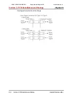
• Note: Using Type I or Type V, a system loop back test can be performed by
connecting CN100 to CN200.
CN100
E
®
M
®
R
®
T
®
CN200
M
E
R
T
CÔNG TY VIỄN THÔNG VIỆT PRO
Chuyên phân phối tổng đài NEC
http://vietpro.com.vn

