


XR12 Troubleshooting Manual
Responding to alarms
Issue 3.0 2009-07-28
Page 1-7
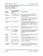
Int. Serial Fail
SD: Exciter
RI:
Exciter Fail
This alarm occurs when there is no
communication with the remote interface PWB
for 2 seconds. See
Low B+
Voltage
SD: AC Mains
RI:
Low B
+
This alarm is triggered if the B
+
voltage falls
below its factory-set threshold. See
Low Backup
Battery
RI:
Memory Battery
Alarm
This alarm is triggered when the voltage of the
backup battery has fallen below an acceptable
level. See
LVPS Fault
SD: Low Voltage Power
Supply
RI:
LVPS Fail
The +24 V, +15 V, -15 V and +5 V power
supplies are monitored. This fault is reported if
one or more of these voltages exceeds its
specified limits. See
Mod Driver
Fail A
SD: Exciter
RI:
Exciter Fail
This fail is reported if the modulator drive on
exciter A is inoperative due to a high duty cycle.
See
Mod Driver
Fail B
SD: Exciter
RI:
Exciter Fail
This fail is reported if the modulator drive on
exciter B is inoperative due to a high duty cycle.
See
Mod.
Protection
SD: External Alarm
This fail is reported from the remote interface
PWB to prevent overmodulation. See
PDM Drive
Fail
SD: Exciter
RI:
Exciter Fail
This fail indicates that the PDM drive on the
active exciter is inoperative due to a low duty
cycle. See
PM Fault A
SD: IPA/PA
RI:
Power Mod Fail
This alarm is triggered when power module A
reports a fault. See
.
PM Fault B
SD: IPA/PA
RI:
Power Mod Fail
This alarm is triggered when RF power module
B reports a fault. See
.
PM Fault C
SD: IPA/PA
RI:
Power Mod Fail
This alarm is triggered when optional RF power
module C reports a fault. See
Status
Message
System Diagram LEDs
Remote Interface
Alarms
Description/Action
Содержание XR12
Страница 2: ......
Страница 4: ......
Страница 8: ...XR12 Troubleshooting Manual Table of contents Page viii Issue 3 0 2009 07 28...
Страница 12: ...XR12 Troubleshooting Manual Page xii Issue 3 0 2009 07 28...
Страница 20: ...XR12 Troubleshooting Manual Page xx Issue 3 0 2009 07 28...
Страница 100: ...XR12 Troubleshooting Manual Detailed Circuit Descriptions Page 2 32 Issue 3 0 2009 07 28...
Страница 108: ...XR12 Troubleshooting Manual Parts Lists Page 3 8 Issue 3 0 2009 07 28...
Страница 196: ......
Страница 214: ...XR12 Troubleshooting Manual Reading Electrical Schematics Page 5 6 Issue 3 0 2009 07 28...
Страница 223: ...Issue 3 1 2014 05 07 SD 9 Figure SD 9 NAPX05E 02 Dynamic Carrier Control PWB Sheet 1of 2...
Страница 224: ...Issue 3 1 2014 05 07 SD 10 Figure SD 10 NAPX05E 02 Dynamic Carrier Control PWB Sheet 2 of 2...
Страница 233: ...Issue 3 1 2014 05 07 SD 19 Figure SD 19 NAP34A RF Power Module Overall Sheet 1 of 2...
Страница 234: ...Issue 3 1 2014 05 07 SD 20 Figure SD 20 NAP34A RF Power Module Modulator Stage Sheet 2 of 2...
Страница 235: ...Issue 3 1 2014 05 07 SD 21 Figure SD 21 NAPC150A RF Drive Control PWB Sheet 1 of 3...
Страница 236: ...Issue 3 1 2014 05 07 SD 22 Figure SD 22 NAPC150A RF Drive Control PWB Sheet 2 of 3...
Страница 237: ...Issue 3 1 2014 05 07 SD 23 Figure SD 23 NAPC150A RF Drive Control PWB Sheet 3 of 3...
Страница 238: ...Issue 3 1 2014 05 07 SD 24 Figure SD 24 NASM07H Modulator Assembly...
Страница 239: ...Issue 3 1 2014 05 07 SD 25 Figure SD 25 NAA51A 03 RF Amplifier Assembly...
Страница 245: ...Issue 3 1 2014 05 07 SD 31 Figure SD 31 NAPS10C RF Drive Power Supply PWB...
Страница 248: ...Issue 3 0 2009 07 28 MD 1 Figure MD 1 XR12 Transmitter...
Страница 249: ...Issue 3 0 2009 07 28 MD 2 Figure MD 2 NAC113B Control Panel Rear View A1 Control Display PWB A2 DCC PWB optional...
Страница 251: ...Issue 3 0 2009 07 28 MD 4 Figure MD 4 NAPX05E 02 Dynamic Carrier Control PWB optional NAPX05E 01 shown NAPX05E 02...
Страница 257: ...Issue 3 0 2009 07 28 MD 10 Figure MD 10 NAPP02 01A RF Current Probe PWB...
Страница 259: ...Issue 3 0 2009 07 28 MD 12 Figure MD 12 NAFP103 05 Forward Reflected Power Probe A1 DETAIL...
Страница 263: ...Issue 3 0 2009 07 28 MD 16 Figure MD 16 NAPC150A RF Drive Control PWB...
Страница 265: ...Issue 3 0 2009 07 28 MD 18 Figure MD 18 NASM07H Modulator Assembly...
Страница 266: ...Issue 3 0 2009 07 28 MD 19 Figure MD 19 PA Input Output PWB 176 1065 04 and 05...
Страница 267: ...Issue 3 0 2009 07 28 MD 20 Figure MD 20 NAA51A 03 RF Amplifier Assembly...
Страница 268: ...Issue 3 0 2009 07 28 MD 21 Figure MD 21 NAPI47B Modulator Input Output PWB...
Страница 271: ...Issue 3 0 2009 07 28 MD 24 Figure MD 24 Relay Assy 202 7019...
Страница 272: ...Issue 3 0 2009 07 28 MD 25 Figure MD 25 Fan Tray 202 7020 J1 B1 B2...
Страница 273: ...Issue 3 0 2009 07 28 MD 26 Figure MD 26 NAPS10C RF Drive Power Supply 62 V...
Страница 275: ...Issue 3 0 2009 07 28 MD 28 Figure MD 28 Rectifier Assembly 202 7017...
Страница 282: ......