


XR12 Troubleshooting Manual
Responding to alarms
Issue 3.0 2009-07-28
Page 1-21
The fault may be caused by a weak battery, or a fault in the detection or alarm circuitry on the
control/display PWB. If the alarm remains after the battery is replaced, suspect the control/display
PWB circuitry.
Removing and reinstalling RF power modules
Removing an RF power module
for this procedure.
1.
An RF power module must be inhibited prior to its removal from the transmitter.
Press and then release the module’s
INHIBIT
switch on the bottom of the module’s front
panel.
•
Make sure that the module’s
INHIBIT/TEMP
alarm LED at the top of the module’s front
panel turns on.
2. Disconnect the cable from J1 at the bottom of the module’s front panel. You should hear a
relay in the rear of the transmitter pick up (turn on). If the module is a spare module that was
not selected for operation, no relay pickup will be heard.
3. Remove both mounting screws from the top of the module’s front panel.
4. Remove the mounting screw behind J1 at bottom of the module’s front panel.
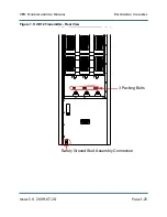
5. If the packing bolt at the rear of the module has not already been removed, press
RF Off
,
switch off ac power, remove the upper transmitter cover, then remove the packing bolt.
Make sure to replace the cover before restoring ac power and
RF On
status.
NOTE:
Batteries should be replaced once a year or as soon as weak batteries cause the
Low Backup
Battery
alarm to turn on. This helps prevent chemical dripping from an old battery, and to
ensure adequate backup voltage for the control/display PWB's microcontroller when the ac
power is turned off.
NOTE:
The RF power module will shut down when the
RF FAIL
or
INHIBIT/TEMP
alarms are
registered on its front panel.
Содержание XR12
Страница 2: ......
Страница 4: ......
Страница 8: ...XR12 Troubleshooting Manual Table of contents Page viii Issue 3 0 2009 07 28...
Страница 12: ...XR12 Troubleshooting Manual Page xii Issue 3 0 2009 07 28...
Страница 20: ...XR12 Troubleshooting Manual Page xx Issue 3 0 2009 07 28...
Страница 100: ...XR12 Troubleshooting Manual Detailed Circuit Descriptions Page 2 32 Issue 3 0 2009 07 28...
Страница 108: ...XR12 Troubleshooting Manual Parts Lists Page 3 8 Issue 3 0 2009 07 28...
Страница 196: ......
Страница 214: ...XR12 Troubleshooting Manual Reading Electrical Schematics Page 5 6 Issue 3 0 2009 07 28...
Страница 223: ...Issue 3 1 2014 05 07 SD 9 Figure SD 9 NAPX05E 02 Dynamic Carrier Control PWB Sheet 1of 2...
Страница 224: ...Issue 3 1 2014 05 07 SD 10 Figure SD 10 NAPX05E 02 Dynamic Carrier Control PWB Sheet 2 of 2...
Страница 233: ...Issue 3 1 2014 05 07 SD 19 Figure SD 19 NAP34A RF Power Module Overall Sheet 1 of 2...
Страница 234: ...Issue 3 1 2014 05 07 SD 20 Figure SD 20 NAP34A RF Power Module Modulator Stage Sheet 2 of 2...
Страница 235: ...Issue 3 1 2014 05 07 SD 21 Figure SD 21 NAPC150A RF Drive Control PWB Sheet 1 of 3...
Страница 236: ...Issue 3 1 2014 05 07 SD 22 Figure SD 22 NAPC150A RF Drive Control PWB Sheet 2 of 3...
Страница 237: ...Issue 3 1 2014 05 07 SD 23 Figure SD 23 NAPC150A RF Drive Control PWB Sheet 3 of 3...
Страница 238: ...Issue 3 1 2014 05 07 SD 24 Figure SD 24 NASM07H Modulator Assembly...
Страница 239: ...Issue 3 1 2014 05 07 SD 25 Figure SD 25 NAA51A 03 RF Amplifier Assembly...
Страница 245: ...Issue 3 1 2014 05 07 SD 31 Figure SD 31 NAPS10C RF Drive Power Supply PWB...
Страница 248: ...Issue 3 0 2009 07 28 MD 1 Figure MD 1 XR12 Transmitter...
Страница 249: ...Issue 3 0 2009 07 28 MD 2 Figure MD 2 NAC113B Control Panel Rear View A1 Control Display PWB A2 DCC PWB optional...
Страница 251: ...Issue 3 0 2009 07 28 MD 4 Figure MD 4 NAPX05E 02 Dynamic Carrier Control PWB optional NAPX05E 01 shown NAPX05E 02...
Страница 257: ...Issue 3 0 2009 07 28 MD 10 Figure MD 10 NAPP02 01A RF Current Probe PWB...
Страница 259: ...Issue 3 0 2009 07 28 MD 12 Figure MD 12 NAFP103 05 Forward Reflected Power Probe A1 DETAIL...
Страница 263: ...Issue 3 0 2009 07 28 MD 16 Figure MD 16 NAPC150A RF Drive Control PWB...
Страница 265: ...Issue 3 0 2009 07 28 MD 18 Figure MD 18 NASM07H Modulator Assembly...
Страница 266: ...Issue 3 0 2009 07 28 MD 19 Figure MD 19 PA Input Output PWB 176 1065 04 and 05...
Страница 267: ...Issue 3 0 2009 07 28 MD 20 Figure MD 20 NAA51A 03 RF Amplifier Assembly...
Страница 268: ...Issue 3 0 2009 07 28 MD 21 Figure MD 21 NAPI47B Modulator Input Output PWB...
Страница 271: ...Issue 3 0 2009 07 28 MD 24 Figure MD 24 Relay Assy 202 7019...
Страница 272: ...Issue 3 0 2009 07 28 MD 25 Figure MD 25 Fan Tray 202 7020 J1 B1 B2...
Страница 273: ...Issue 3 0 2009 07 28 MD 26 Figure MD 26 NAPS10C RF Drive Power Supply 62 V...
Страница 275: ...Issue 3 0 2009 07 28 MD 28 Figure MD 28 Rectifier Assembly 202 7017...
Страница 282: ......