


XR12 Troubleshooting Manual
Detailed Circuit Descriptions
Issue 3.0 2009-07-28
Page 2-15
Modulation level detector
The modulation level detector circuit monitors the on/off times of the
Forward Power Sample
input
(J13-3) for excessive on times. It automatically inhibits a portion of any modulating audio's positive
going half-cycle that would cause excessive 'on times' and results in the stress current threshold of the
transmitter's RF power amplifier stages being exceeded. The circuit consists of comparators U32A,
U32B, U32C, U32D, U33A, U33B and associated components. It provides a discharge path to -15 V
for C137 when the 'on time' of the F
orward Power Sample
input will result in modulation peaks that
exceed safe operating levels.
The
Forward Power Sample
input, applied to the inverting inputs of each comparator, is a varying
positive dc voltage directly proportional to the RF output's modulation envelope. The audio
component is synchronized with the audio output of U33C and is the most positive at the peak of the
modulating audio's positive half-cycle.
Each comparator has a reference voltage applied to its non-inverting input that represents the RF
stress current threshold for a specific carrier level/audio amplitude/audio frequency combination
(see
).
MOD PROT THRESHOLD
potentiometer R165 is adjusted to precisely set the
threshold voltages, when the PWB is installed in a transmitter.
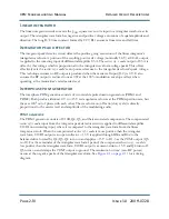
When the voltage representing the modulation envelope exceeds the RF stress current threshold of a
comparator, that comparator connects its output resistor to -15 V and provides a discharge path for
C137. The time for C137 to discharge to a negative voltage is dictated by the number of resistors
connected to -15 V (modulation amplitude) and the period of time they are connected (audio
frequency). C137's discharge time (dictated by the R/C time constant) is progressively faster as the
modulation depth increases (more comparator thresholds are exceeded) and it has a longer time to
discharge as the audio frequency decreases. See
for the duration of a positive half-cycle at
the lowest unaffected audio frequency for specific modulation depths.
Table 2.1: Peak Modulation Limit Threshold
Mod Depth
Peak %
Lowest Unaffected
Freq (Hz)
Duration (ms)
85
10
50.0
95
11
46.6
105
20
25.6
115
32
15.4
125
56
8.9
135
96
5.2
Содержание XR12
Страница 2: ......
Страница 4: ......
Страница 8: ...XR12 Troubleshooting Manual Table of contents Page viii Issue 3 0 2009 07 28...
Страница 12: ...XR12 Troubleshooting Manual Page xii Issue 3 0 2009 07 28...
Страница 20: ...XR12 Troubleshooting Manual Page xx Issue 3 0 2009 07 28...
Страница 100: ...XR12 Troubleshooting Manual Detailed Circuit Descriptions Page 2 32 Issue 3 0 2009 07 28...
Страница 108: ...XR12 Troubleshooting Manual Parts Lists Page 3 8 Issue 3 0 2009 07 28...
Страница 196: ......
Страница 214: ...XR12 Troubleshooting Manual Reading Electrical Schematics Page 5 6 Issue 3 0 2009 07 28...
Страница 223: ...Issue 3 1 2014 05 07 SD 9 Figure SD 9 NAPX05E 02 Dynamic Carrier Control PWB Sheet 1of 2...
Страница 224: ...Issue 3 1 2014 05 07 SD 10 Figure SD 10 NAPX05E 02 Dynamic Carrier Control PWB Sheet 2 of 2...
Страница 233: ...Issue 3 1 2014 05 07 SD 19 Figure SD 19 NAP34A RF Power Module Overall Sheet 1 of 2...
Страница 234: ...Issue 3 1 2014 05 07 SD 20 Figure SD 20 NAP34A RF Power Module Modulator Stage Sheet 2 of 2...
Страница 235: ...Issue 3 1 2014 05 07 SD 21 Figure SD 21 NAPC150A RF Drive Control PWB Sheet 1 of 3...
Страница 236: ...Issue 3 1 2014 05 07 SD 22 Figure SD 22 NAPC150A RF Drive Control PWB Sheet 2 of 3...
Страница 237: ...Issue 3 1 2014 05 07 SD 23 Figure SD 23 NAPC150A RF Drive Control PWB Sheet 3 of 3...
Страница 238: ...Issue 3 1 2014 05 07 SD 24 Figure SD 24 NASM07H Modulator Assembly...
Страница 239: ...Issue 3 1 2014 05 07 SD 25 Figure SD 25 NAA51A 03 RF Amplifier Assembly...
Страница 245: ...Issue 3 1 2014 05 07 SD 31 Figure SD 31 NAPS10C RF Drive Power Supply PWB...
Страница 248: ...Issue 3 0 2009 07 28 MD 1 Figure MD 1 XR12 Transmitter...
Страница 249: ...Issue 3 0 2009 07 28 MD 2 Figure MD 2 NAC113B Control Panel Rear View A1 Control Display PWB A2 DCC PWB optional...
Страница 251: ...Issue 3 0 2009 07 28 MD 4 Figure MD 4 NAPX05E 02 Dynamic Carrier Control PWB optional NAPX05E 01 shown NAPX05E 02...
Страница 257: ...Issue 3 0 2009 07 28 MD 10 Figure MD 10 NAPP02 01A RF Current Probe PWB...
Страница 259: ...Issue 3 0 2009 07 28 MD 12 Figure MD 12 NAFP103 05 Forward Reflected Power Probe A1 DETAIL...
Страница 263: ...Issue 3 0 2009 07 28 MD 16 Figure MD 16 NAPC150A RF Drive Control PWB...
Страница 265: ...Issue 3 0 2009 07 28 MD 18 Figure MD 18 NASM07H Modulator Assembly...
Страница 266: ...Issue 3 0 2009 07 28 MD 19 Figure MD 19 PA Input Output PWB 176 1065 04 and 05...
Страница 267: ...Issue 3 0 2009 07 28 MD 20 Figure MD 20 NAA51A 03 RF Amplifier Assembly...
Страница 268: ...Issue 3 0 2009 07 28 MD 21 Figure MD 21 NAPI47B Modulator Input Output PWB...
Страница 271: ...Issue 3 0 2009 07 28 MD 24 Figure MD 24 Relay Assy 202 7019...
Страница 272: ...Issue 3 0 2009 07 28 MD 25 Figure MD 25 Fan Tray 202 7020 J1 B1 B2...
Страница 273: ...Issue 3 0 2009 07 28 MD 26 Figure MD 26 NAPS10C RF Drive Power Supply 62 V...
Страница 275: ...Issue 3 0 2009 07 28 MD 28 Figure MD 28 Rectifier Assembly 202 7017...
Страница 282: ......