


XR12 Troubleshooting Manual
Responding to alarms
Page 1-2
Issue 3.0 2009-07-28
Remote troubleshooting
Remote on-air troubleshooting consists of monitoring the transmitter's radiated signal using an on-air
monitor, and observing the status of each remote fault alarm indicator. Information obtained from
these sources should enable an operator to decide whether an alarm response may be deferred to a
more convenient time, an immediate corrective action must be taken, or if a standby transmitter must
be enabled (if one is available). It is recommended that the significance of remote indications, and the
appropriate responses, be incorporated into a station's standard operating procedures. Refer to
“Identifying an alarm” on page 1-4
to determine the remedial action required for a given fault.
Local troubleshooting
Local on-air troubleshooting consists of monitoring the transmitter's integral meters and fault alarm
indicators. Analysis of this data will normally identify the type of fault, and in most cases will
determine what corrective action must be taken. Refer to
“Identifying an alarm” on page 1-4
to
determine the remedial action required for a given fault.
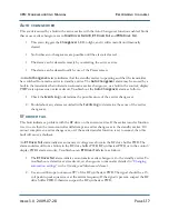
The power amplifier stage contains an integral modular reserve (IMR) feature. This feature permits
the transmitter to operate at a reduced RF output level when a malfunction occurs in one of its power
modules. Station operating procedures will dictate whether a reduced RF output level is acceptable.
When a reduced RF output level can be tolerated, replacement of the defective RF power module
may be deferred to a convenient time.
A defective RF power module may be removed from the transmitter for servicing, while the
transmitter is operating, provided that the conditions in the removal instructions detailed in
“Removing an RF power module” on page 1-21
Off-air troubleshooting
Off-air troubleshooting must be performed when the replacement of a defective RF power amplifier
module, or routine on-air calibration adjustments, will not restore operation.
It is recommended that the transmitter’s output be connected to a precision 50
Ω
resistive dummy
load (rated for at least the maximum transmitter power rating) before starting off-air troubleshooting
procedures. If an appropriate dummy load is not available, troubleshooting for a majority of faults
can be performed with RF power stage turned off. The transmitter may remain connected to its
antenna system for these procedures.
NOTE:
Reduce the RF output level to a minimal value when troubleshooting faults in the power
amplifier stage while the transmitter’s RF output is connected to the antenna system.
Содержание XR12
Страница 2: ......
Страница 4: ......
Страница 8: ...XR12 Troubleshooting Manual Table of contents Page viii Issue 3 0 2009 07 28...
Страница 12: ...XR12 Troubleshooting Manual Page xii Issue 3 0 2009 07 28...
Страница 20: ...XR12 Troubleshooting Manual Page xx Issue 3 0 2009 07 28...
Страница 100: ...XR12 Troubleshooting Manual Detailed Circuit Descriptions Page 2 32 Issue 3 0 2009 07 28...
Страница 108: ...XR12 Troubleshooting Manual Parts Lists Page 3 8 Issue 3 0 2009 07 28...
Страница 196: ......
Страница 214: ...XR12 Troubleshooting Manual Reading Electrical Schematics Page 5 6 Issue 3 0 2009 07 28...
Страница 223: ...Issue 3 1 2014 05 07 SD 9 Figure SD 9 NAPX05E 02 Dynamic Carrier Control PWB Sheet 1of 2...
Страница 224: ...Issue 3 1 2014 05 07 SD 10 Figure SD 10 NAPX05E 02 Dynamic Carrier Control PWB Sheet 2 of 2...
Страница 233: ...Issue 3 1 2014 05 07 SD 19 Figure SD 19 NAP34A RF Power Module Overall Sheet 1 of 2...
Страница 234: ...Issue 3 1 2014 05 07 SD 20 Figure SD 20 NAP34A RF Power Module Modulator Stage Sheet 2 of 2...
Страница 235: ...Issue 3 1 2014 05 07 SD 21 Figure SD 21 NAPC150A RF Drive Control PWB Sheet 1 of 3...
Страница 236: ...Issue 3 1 2014 05 07 SD 22 Figure SD 22 NAPC150A RF Drive Control PWB Sheet 2 of 3...
Страница 237: ...Issue 3 1 2014 05 07 SD 23 Figure SD 23 NAPC150A RF Drive Control PWB Sheet 3 of 3...
Страница 238: ...Issue 3 1 2014 05 07 SD 24 Figure SD 24 NASM07H Modulator Assembly...
Страница 239: ...Issue 3 1 2014 05 07 SD 25 Figure SD 25 NAA51A 03 RF Amplifier Assembly...
Страница 245: ...Issue 3 1 2014 05 07 SD 31 Figure SD 31 NAPS10C RF Drive Power Supply PWB...
Страница 248: ...Issue 3 0 2009 07 28 MD 1 Figure MD 1 XR12 Transmitter...
Страница 249: ...Issue 3 0 2009 07 28 MD 2 Figure MD 2 NAC113B Control Panel Rear View A1 Control Display PWB A2 DCC PWB optional...
Страница 251: ...Issue 3 0 2009 07 28 MD 4 Figure MD 4 NAPX05E 02 Dynamic Carrier Control PWB optional NAPX05E 01 shown NAPX05E 02...
Страница 257: ...Issue 3 0 2009 07 28 MD 10 Figure MD 10 NAPP02 01A RF Current Probe PWB...
Страница 259: ...Issue 3 0 2009 07 28 MD 12 Figure MD 12 NAFP103 05 Forward Reflected Power Probe A1 DETAIL...
Страница 263: ...Issue 3 0 2009 07 28 MD 16 Figure MD 16 NAPC150A RF Drive Control PWB...
Страница 265: ...Issue 3 0 2009 07 28 MD 18 Figure MD 18 NASM07H Modulator Assembly...
Страница 266: ...Issue 3 0 2009 07 28 MD 19 Figure MD 19 PA Input Output PWB 176 1065 04 and 05...
Страница 267: ...Issue 3 0 2009 07 28 MD 20 Figure MD 20 NAA51A 03 RF Amplifier Assembly...
Страница 268: ...Issue 3 0 2009 07 28 MD 21 Figure MD 21 NAPI47B Modulator Input Output PWB...
Страница 271: ...Issue 3 0 2009 07 28 MD 24 Figure MD 24 Relay Assy 202 7019...
Страница 272: ...Issue 3 0 2009 07 28 MD 25 Figure MD 25 Fan Tray 202 7020 J1 B1 B2...
Страница 273: ...Issue 3 0 2009 07 28 MD 26 Figure MD 26 NAPS10C RF Drive Power Supply 62 V...
Страница 275: ...Issue 3 0 2009 07 28 MD 28 Figure MD 28 Rectifier Assembly 202 7017...
Страница 282: ......