


XR12 Troubleshooting Manual
Responding to alarms
Issue 3.0 2009-07-28
Page 1-15
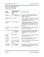
An output network VSWR alarm can be caused by excessive reflected power, a fault in the forward/
reflected power probe assembly or a fault in the system control PWB's alarm circuitry. Troubleshoot
a VSWR alarm as follows.
1. Read the forward and reflected power from the diagnostic display’s
Meters
screen. If the
forward power has been reduced and the reflected power meter indicates reflected power,
there may be a matching problem between antenna and transmitter (de-tuned load, arcing or
poor bandwidth.
2. Perform a visual inspection of the antenna feed line and antenna and correct any obvious
problems that can cause excessive reflected power.
3. If there are no obvious problems between transmitter and antenna, measure the voltage at
TP1 and TP2 of the control/display PWB. If the voltage at TP2 is greater than 30% of TP1,
suspect the forward/reflected power probe. Otherwise suspect the control/display PWB.
Total power limit
This fail is triggered when the product of the B+ (dc) voltage and the dc current is greater than the
limit set in software. For the XR12 the threshold is 22 kVA. This fail causes an immediate cutback
(power reduction), but not a shutback.
Mod driver fail A
This alarm is reported to the microcontroller only if exciter A is selected. If the exciter transfer
function is set to
auto
then the microcontroller will attempt a changeover to exciter B. If it cannot or
if the exciter transfer function is set to manual, then this fault will cause a shutback.
This alarm indicates the PDM duty cycle of exciter A’s modulator drive is too high. Try to reset the
alarm. If the alarm persists, proceed to the steps listed in
.
Mod driver fail B
This alarm is reported to the microcontroller only if exciter B is selected. If the exciter transfer
function is set to
auto
then the microcontroller will attempt a changeover to exciter A. If it cannot or
if the exciter transfer function is set to manual, then this fault will cause a shutback.
NOTE:
A VSWR alarm will always cause a SHUTBACK. If the problem occurs three times within
five seconds, the transmitter shall be in CUTBACK mode to reduce RF output power until the
VSWR alarm no longer exists.
Содержание XR12
Страница 2: ......
Страница 4: ......
Страница 8: ...XR12 Troubleshooting Manual Table of contents Page viii Issue 3 0 2009 07 28...
Страница 12: ...XR12 Troubleshooting Manual Page xii Issue 3 0 2009 07 28...
Страница 20: ...XR12 Troubleshooting Manual Page xx Issue 3 0 2009 07 28...
Страница 100: ...XR12 Troubleshooting Manual Detailed Circuit Descriptions Page 2 32 Issue 3 0 2009 07 28...
Страница 108: ...XR12 Troubleshooting Manual Parts Lists Page 3 8 Issue 3 0 2009 07 28...
Страница 196: ......
Страница 214: ...XR12 Troubleshooting Manual Reading Electrical Schematics Page 5 6 Issue 3 0 2009 07 28...
Страница 223: ...Issue 3 1 2014 05 07 SD 9 Figure SD 9 NAPX05E 02 Dynamic Carrier Control PWB Sheet 1of 2...
Страница 224: ...Issue 3 1 2014 05 07 SD 10 Figure SD 10 NAPX05E 02 Dynamic Carrier Control PWB Sheet 2 of 2...
Страница 233: ...Issue 3 1 2014 05 07 SD 19 Figure SD 19 NAP34A RF Power Module Overall Sheet 1 of 2...
Страница 234: ...Issue 3 1 2014 05 07 SD 20 Figure SD 20 NAP34A RF Power Module Modulator Stage Sheet 2 of 2...
Страница 235: ...Issue 3 1 2014 05 07 SD 21 Figure SD 21 NAPC150A RF Drive Control PWB Sheet 1 of 3...
Страница 236: ...Issue 3 1 2014 05 07 SD 22 Figure SD 22 NAPC150A RF Drive Control PWB Sheet 2 of 3...
Страница 237: ...Issue 3 1 2014 05 07 SD 23 Figure SD 23 NAPC150A RF Drive Control PWB Sheet 3 of 3...
Страница 238: ...Issue 3 1 2014 05 07 SD 24 Figure SD 24 NASM07H Modulator Assembly...
Страница 239: ...Issue 3 1 2014 05 07 SD 25 Figure SD 25 NAA51A 03 RF Amplifier Assembly...
Страница 245: ...Issue 3 1 2014 05 07 SD 31 Figure SD 31 NAPS10C RF Drive Power Supply PWB...
Страница 248: ...Issue 3 0 2009 07 28 MD 1 Figure MD 1 XR12 Transmitter...
Страница 249: ...Issue 3 0 2009 07 28 MD 2 Figure MD 2 NAC113B Control Panel Rear View A1 Control Display PWB A2 DCC PWB optional...
Страница 251: ...Issue 3 0 2009 07 28 MD 4 Figure MD 4 NAPX05E 02 Dynamic Carrier Control PWB optional NAPX05E 01 shown NAPX05E 02...
Страница 257: ...Issue 3 0 2009 07 28 MD 10 Figure MD 10 NAPP02 01A RF Current Probe PWB...
Страница 259: ...Issue 3 0 2009 07 28 MD 12 Figure MD 12 NAFP103 05 Forward Reflected Power Probe A1 DETAIL...
Страница 263: ...Issue 3 0 2009 07 28 MD 16 Figure MD 16 NAPC150A RF Drive Control PWB...
Страница 265: ...Issue 3 0 2009 07 28 MD 18 Figure MD 18 NASM07H Modulator Assembly...
Страница 266: ...Issue 3 0 2009 07 28 MD 19 Figure MD 19 PA Input Output PWB 176 1065 04 and 05...
Страница 267: ...Issue 3 0 2009 07 28 MD 20 Figure MD 20 NAA51A 03 RF Amplifier Assembly...
Страница 268: ...Issue 3 0 2009 07 28 MD 21 Figure MD 21 NAPI47B Modulator Input Output PWB...
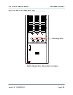
Страница 271: ...Issue 3 0 2009 07 28 MD 24 Figure MD 24 Relay Assy 202 7019...
Страница 272: ...Issue 3 0 2009 07 28 MD 25 Figure MD 25 Fan Tray 202 7020 J1 B1 B2...
Страница 273: ...Issue 3 0 2009 07 28 MD 26 Figure MD 26 NAPS10C RF Drive Power Supply 62 V...
Страница 275: ...Issue 3 0 2009 07 28 MD 28 Figure MD 28 Rectifier Assembly 202 7017...
Страница 282: ......