


XR12 Installation Manual
Control and monitoring
Page 9-12
Issue 3.0 2009-07-15
RF monitor sample.
A true sample of the RF output voltage waveform is available through the J8
BNC connector (RF MONITOR) on the remote interface PWB. The RF monitor output is intended
to be applied to a station modulation monitor with a 50
Ω
input impedance. It may also be monitored
by an oscilloscope during maintenance procedures. The RF monitor output can be set to provide
1.0 V rms or 5.0 V rms for each preset power level, provided they are preset to a level that is between
1 kW and 12 kW.
LAN interface (NxLink)
A serial port is available on 9-pin D-sub connector J12 of the XR12’s remote interface PWB. This
port allows you to remotely control and interrogate the XR12’s operational status. If the NxLink
Ethernet interface module option is installed and you wish to use it as the remote interface,
connector J12 is linked to Port 1 of the NxLink module. Refer to the
NxLink Technical Instructions
Manual
for further details on the NxLink module.
Note: Some older modulation monitors may not accept a 1 V input.
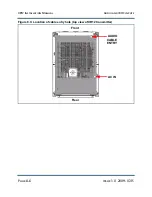
Note: The output level range is determined by the setting of the BYPASS/GAIN
switch. When the switch is set BYPASS, the RF monitor sample voltage is a
nominal 1 V rms. When the switch is set to GAIN, the RF monitor sample voltage
increases to a nominal 5 V rms
.
The rms output level is adjusted from the GUI.
Setting the level higher than the limit determined by the BYPASS/GAIN switch
[1 V rms or 5 V rms (carrier)] will cause distortion in the waveform, and may
prevent accurate measurement of the modulation depth.
Содержание XR12
Страница 1: ...XR12 Transmitter Installation Manual Document XR12 INST Issue 3 0 2009 07 15 Status Preliminary...
Страница 2: ......
Страница 4: ......
Страница 16: ...XR12 Installation Manual Page xvi Issue 3 0 2009 07 15...
Страница 22: ...XR12 Installation Manual Unpacking and positioning Page 2 4 Issue 3 0 2009 07 15...
Страница 26: ...XR12 Installation Manual Installing the power transformer Page 3 4 Issue 3 0 2009 07 15...
Страница 36: ...XR12 Installation Manual Installing the RF connector Page 6 6 Issue 3 0 2009 07 15...
Страница 48: ...XR12 Installation Manual Adjusting the spark gap Page 7 12 Issue 3 0 2009 07 15...
Страница 78: ...XR12 Installation Manual Parts and tools Page 12 4 Issue 3 0 2009 07 15...
Страница 91: ......


