


XR12 Installation Manual
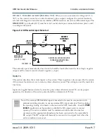
Audio and IBOC inputs
Page 8-4
Issue 3.0 2009-07-15
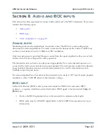
•
If you provide a backup analog program stream to an exciter configured as
analog
in an IBOC
installation, the system can automatically switch to the backup analog exciter and audio
program stream. Refer to the
XR12 Operating and Maintenance Manual
for information about
setting up exciter changeover.
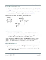
Configuring Exciter A for IBOC
1. On the remote interface PWB, set the
IBOC Input Select A
input to single-ended
configuration by setting
E19
to
2-3
.
2. On the remote interface PWB, connect a jumper from
J3-23
to ground (
TB2-4
) permanently
(or through the remote system), and set
J3-25
to open circuit. This will enable the IBOC
inputs on
Exciter A
. A connector shell and solder pins for
J3
are provided in the ancillary kit.
3. On the RF drive buffer PWB, set
E3
to
Low
to select low sensitivity by shorting pins 2 and 3.
4. On the RF drive buffer PWB, set
E1
to
Ext
by shorting pins 2 and 3, and
E2
to
Int
by
shorting pins 1 and 2.
Configuring Exciter B for IBOC
1. On the remote interface PWB, set the
IBOC Input Select B
input to single-ended
configuration by setting
E19
to
2-3
.
2. On the remote interface PWB, connect a jumper from
J3-25
to ground (
TB2-4
) permanently
(or through the remote system), and set
J3-23
to open circuit. This will enable the IBOC
inputs on
Exciter B
. A connecter shell and solder pins for
J3
are provided in the ancillary kit.
3. On the RF drive buffer PWB, set
E3
to
Low
to select low sensitivity by shorting pins 2 and 3.
4. On the RF drive buffer PWB, set
E1
to
Int
by shorting pins 1 and 2, and
E2
to
Ext
by
shorting pins 2 and 3.
Configuring both Exciter A and B for IBOC
•
If both exciters are driven from the NE-IBOC, the NE-IBOC becomes a potential single
point of failure in the system.
See “IBOC Configuration” on page 8-3.
1. On the remote interface PWB, set the
IBOC Input Select A
and the
IBOC Input Select B
inputs to single-ended configuration by setting
E19
to
2-3
.
Содержание XR12
Страница 1: ...XR12 Transmitter Installation Manual Document XR12 INST Issue 3 0 2009 07 15 Status Preliminary...
Страница 2: ......
Страница 4: ......
Страница 16: ...XR12 Installation Manual Page xvi Issue 3 0 2009 07 15...
Страница 22: ...XR12 Installation Manual Unpacking and positioning Page 2 4 Issue 3 0 2009 07 15...
Страница 26: ...XR12 Installation Manual Installing the power transformer Page 3 4 Issue 3 0 2009 07 15...
Страница 36: ...XR12 Installation Manual Installing the RF connector Page 6 6 Issue 3 0 2009 07 15...
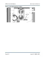
Страница 48: ...XR12 Installation Manual Adjusting the spark gap Page 7 12 Issue 3 0 2009 07 15...
Страница 78: ...XR12 Installation Manual Parts and tools Page 12 4 Issue 3 0 2009 07 15...
Страница 91: ......