


XR12 Installation Manual
Control and monitoring
Issue 3.0 2009-07-15
Page 9-11
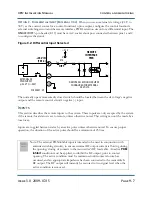
Remote performance monitoring
The transmitter provides outputs that let you monitor RF performance. They include dc voltages that
represent the forward power level, the reflected power level, the B+ voltage and the dc current. In
addition, a true RF sample of the RF output voltage waveform is available for external monitoring.
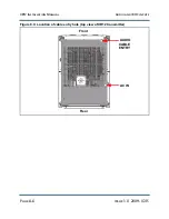
These outputs are provided on the remote interface PWB.
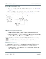
Analog samples
Sample voltages, in the range of 0 to 4 V are provided for the following system parameters:
•
J2-1:
Fwd Power
•
J2-3:
Refld Power
•
J2-5:
B+ Voltage
•
J2-7:
Dc Current
•
J8:
RF Monitor
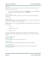
Forward power level.
A buffered dc voltage that reports the forward power level on J2-1. This
voltage is a pure square law function and will be 3.9 ± 0.5 V when the forward power is 12.5 kW. The
monitoring circuit’s impedance must be greater than 1,000 ohms.
Reflected power level.
A buffered dc voltage that reports the reflected power level on J2-3. This
voltage is a pure square law function and will be 3.9 ± 0.5 V when the reflected power is 1,875 W.
The monitoring circuit’s impedance must be greater than 1,000 ohms.
B+ volts.
A buffered dc voltage on J2-5 that is directly proportional to the dc voltage from the main
dc power supply. This voltage will be 3.0 V when the dc voltage being applied to the RF stage is
312 V. The monitoring circuit impedance must be greater than 1,000 ohms.
Dc Current.
A buffered dc voltage on J2-7 that reports the dc current level of the main B+ power
supply. The output is 3.0 ± 0.5 V with a dc current of 100 A.
Содержание XR12
Страница 1: ...XR12 Transmitter Installation Manual Document XR12 INST Issue 3 0 2009 07 15 Status Preliminary...
Страница 2: ......
Страница 4: ......
Страница 16: ...XR12 Installation Manual Page xvi Issue 3 0 2009 07 15...
Страница 22: ...XR12 Installation Manual Unpacking and positioning Page 2 4 Issue 3 0 2009 07 15...
Страница 26: ...XR12 Installation Manual Installing the power transformer Page 3 4 Issue 3 0 2009 07 15...
Страница 36: ...XR12 Installation Manual Installing the RF connector Page 6 6 Issue 3 0 2009 07 15...
Страница 48: ...XR12 Installation Manual Adjusting the spark gap Page 7 12 Issue 3 0 2009 07 15...
Страница 78: ...XR12 Installation Manual Parts and tools Page 12 4 Issue 3 0 2009 07 15...
Страница 91: ......


