


XR12 Installation Manual
Installing the RF connector
Page 6-4
Issue 3.0 2009-07-15
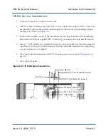
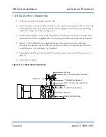
1-5/8 EIA Output Connection
1. Locate and unpack the output connector kit.
2. Attach the brass connector cup from the kit to the output strap using the 5/16 x 1 inch long
socket head cap screw, split washer and flat washer supplied, such that the cup is pointing
towards the large hole in the top (
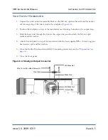
3. Position the stud plate on top of the transmitter over the large hole above the output strap
and attach with the four supplied M5 x 16 mm long pan head screws, split and flat washers.
4. Insert a 1-5/8 EIA Bullet (not supplied) through the connector plate into the brass
connector cup. Remove the four M8 nuts and washers from the stud plate and attach the
output flange or coax connector (not supplied).
5. Close the Exciter Panel and reinstall all 14 mounting screws removed in
6. Close the front panel.
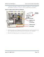
Figure 6.3: 1-5/8 Output Connection
Stud Plate
M8 Nuts
M5 x 16 mm Pan Head Screws (4)
1 5/8 Bullet (Not Included)
5/16 x 1” Socket Head Cap Screw
1-5/8 EIA Cup Connector
5/16 Nut
Output Connector Strap
Содержание XR12
Страница 1: ...XR12 Transmitter Installation Manual Document XR12 INST Issue 3 0 2009 07 15 Status Preliminary...
Страница 2: ......
Страница 4: ......
Страница 16: ...XR12 Installation Manual Page xvi Issue 3 0 2009 07 15...
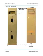
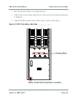
Страница 22: ...XR12 Installation Manual Unpacking and positioning Page 2 4 Issue 3 0 2009 07 15...
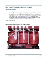
Страница 26: ...XR12 Installation Manual Installing the power transformer Page 3 4 Issue 3 0 2009 07 15...
Страница 36: ...XR12 Installation Manual Installing the RF connector Page 6 6 Issue 3 0 2009 07 15...
Страница 48: ...XR12 Installation Manual Adjusting the spark gap Page 7 12 Issue 3 0 2009 07 15...
Страница 78: ...XR12 Installation Manual Parts and tools Page 12 4 Issue 3 0 2009 07 15...
Страница 91: ......