©
National Instruments Corporation
5
NI 1357/1358/1359 Kit Installation Guide
•
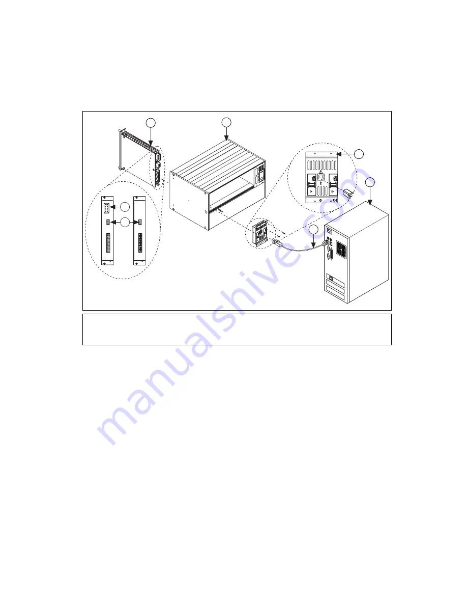
USB kits—Connect one end of the USB cable to the
NI USB-1359 switch controller and the other end to a USB hub
or port on the computer as shown in Figure 5.
Figure 5.
Cabling a USB Switch Controller to a 10-Pin Rear Connector Switch Module
10. To add a chassis to the configuration, refer to the
Configuration
section. If you are
not
creating a multichassis
configuration, refer to the
Configuring the SCXI Switch Module in
MAX
section to configure the switch module.
Multichassis Configuration
Complete the following steps to create a multichassis switch configuration:
1.
Complete the
section, steps 1 through 7, for each
chassis you want to add to the configuration.
2.
Set a distinct address for each chassis. Figure 6 illustrates the address
switches located on the front of the chassis.
1
SCXI Switch
2
HVAB Connector
3
10-Pin Rear Connector
4
USB Cable
5
Computer
6
NI USB-1359
7
NI SCXI-1000/1001 or NI PXI-1010 Chassis
30
0V
M
AX
CA
T II
HV
A
NA
LO
G B
US
300V CA
T II
HV ANALOG
BU
S
300V CA
T II
HV ANALOG
BU
S
N114
N114
300V MAX
CAT II
HV ANALOG BUS
300V MAX
CAT II
HV ANALOG BUS
300V CA
T II
HV ANALOG
BU
S
300V CA
T II
HV ANALOG
BU
S
or
5
1
7
6
4
3
2
Содержание SCXI USB-1357
Страница 1: ...USB 1357...


