National Instruments SCXI-1303, Руководство по эксплуатации и калибровке
Операция и калибровка модуля National Instruments SCXI-1303 описаны в руководстве по эксплуатации и калибровке. Вы можете скачать его бесплатно на manualshive.com. Руководство содержит все необходимые инструкции для успешной работы с продуктом. Не забудьте загрузить его перед началом использования устройства.
Поделиться
Скачать


Отзывы:
Нет отзывов
Похожие инструкции для SCXI-1303

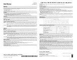
SP-550
Бренд: Partner Страницы: 61

820 KSR
Бренд: Omni Страницы: 288
C680 3G
Бренд: VeriFone Страницы: 2

Glamor Series
Бренд: Datavan Страницы: 67

BOSSTX2B
Бренд: Bosslan Страницы: 87

9420 MID
Бренд: Kaba Страницы: 42

TC603
Бренд: iMotion Страницы: 88

SCXI-1322
Бренд: National Instruments Страницы: 12

Vivopay Neo 2
Бренд: IDTECH Страницы: 523

AN-80i
Бренд: Redline Страницы: 106

ECT
Бренд: Breeze Страницы: 38

CLTI-1MC4
Бренд: Crestron Страницы: 4

DT 600 FH
Бренд: Hafele Страницы: 24

F-1020
Бренд: Mpaio Страницы: 17

HBA127H
Бренд: hager Страницы: 4

776572-1600
Бренд: National Instruments Страницы: 101

Encrypted MSR
Бренд: NCR Страницы: 6

S-615E
Бренд: Datavan Страницы: 49


