4-14
|
ni.com
Chapter 4
Digital Input/Output and PFI
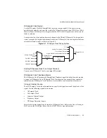
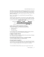
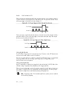
Assume that an input terminal has been low for a long time. The input terminal then changes
from low to high, but glitches several times. When the Filter Clock has sampled the signal high
on
N
consecutive edges, the low-to-high transition is propagated to the rest of the circuit. The
value of
N
depends on the filter setting, as shown in Table 4-1.
On power up, the filters are disabled. Figure 4-7 shows an example of a low-to-high transition
on an input that has a custom filter set to
N
= 5.
Figure 4-7.
PFI Filter Example
Table 4-1.
Selectable PFI Filter Settings
Filter Setting
Filter Clock
Jitter
Min Pulse
Width
*
to
Pass
Max Pulse Width
*
to Not Pass
112.5 ns (short)
80 MHz
12.5 ns
112.5 ns
100 ns
6.4
μ
s
(medium)
80 MHz
12.5 ns
6.4
μ
s
6.3875
μ
s
2.56 ms (high)
100 kHz
10
μ
s
2.56 ms
2.55 ms
Custom
User-configurable
1 Filter
Clock
period
T
user
T
user
- (1 Filter Clock
period)
*
Pulse widths are nominal values; the accuracy of the chassis timebase and I/O distortion will affect
these values.
1
2
3
1
4
1
2
3
4
5
PFI Termin
a
l
Filtered inp
u
t goe
s
high when termin
a
l
i
s
sa
mpled high on
five con
s
ec
u
tive filter
clock
s
.
Filter Clock
Filtered Inp
u
t

