
© National Instruments
|
1-13
NI cDAQ-9181/9184/9188/9191 User Manual
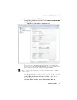
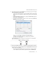
19. If the cDAQ chassis is not reserved automatically, select the chassis and click the
Reserve
Chassis
button. Refer to the
section for more information.
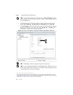
20. Self-test your chassis in MAX by expanding
Devices and Interfaces
, right-clicking
NI cDAQ-
<model number>
, and selecting
Self-Test
. Self-test performs a brief test to
determine successful chassis installation. When the self-test finishes, a message indicates
successful verification or if an error occurred. If an error occurs, refer to
.
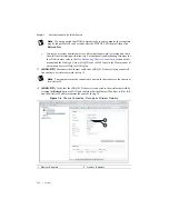
21. Run a Test Panel in MAX by expanding
Devices and Interfaces» NI cDAQ-
<model
number>
, right-clicking your C Series module, and selecting
Test Panels
to open a test
panel for the selected module.
If the test panel displays an error message, refer to
.
Click
Close
to exit the test panel.
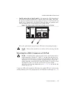
Note
When in use, the cDAQ chassis may become warm to the touch. This is
normal.
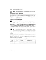
Wiring Power to the cDAQ Chassis
Caution
To ensure the specified EMC performance, do
not
connect the power input
to a DC mains supply or to any supply requiring a connecting cable longer than 3 m
(10 ft). A DC mains supply is a local DC electricity supply network in the
infrastructure of a site or building.
The cDAQ chassis requires an external power source as described in the
Power Requirements
section of the specifications document for your cDAQ chassis. Some suggested NI power
supplies are listed in Table 1-8. The cDAQ chassis filters and regulates the supplied power and
provides power to all of the modules. The green POWER LED on the front panel identifies when
the power input is in use.
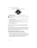
Complete the following steps to connect a power source to the cDAQ chassis.
1.
Make sure the power source is turned off.
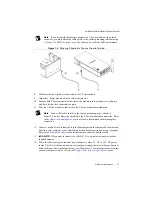
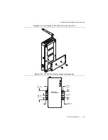
2.
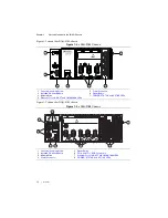
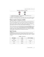
If connected, loosen the connector screw flanges and remove the power screw terminal
connector plug from the cDAQ chassis. Figure 1-9 shows the terminal screws, which secure
the wires in the screw terminals, and the connector screw flanges, which secure the
connector plug on the front panel.


