©
National Instruments Corporation
3
NI 9148 Operating Instructions and Specifications
Caution
Your installation must meet the following requirements for space and cabling
clearance:
•
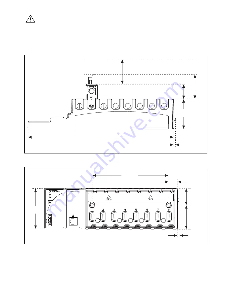
Allow 25.4 mm (1 in.) on the top and the bottom of the chassis for air circulation.
•
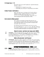
Allow 50.8 mm (2 in.) in front of modules for cabling clearance for common
connectors, such as the 10-terminal, detachable screw terminal connector, as shown
in Figure 2.
Figure 2.
NI 9148, Bottom View with Dimensions
Figure 3.
NI 9148, Front View with Dimensions
29 mm
(1.14 in.)
58.9 mm
(2.
3
2 in.)
48.4 mm
(1.91 in.)
3
.
3
mm
(0.1
3
in.)
286.4 mm
(11.28 in.)
Cabling Clearance
50.8 mm (2.00 in.)
87.
3
mm
(
3
.44 in.)
165.1 mm
(6.50 in.)
3
.1 mm
(0.12 in.)
51.1 mm
(2.04 in.)
3
6.4 mm
(1.4
3
in.)
19 mm
(0.75 in.)
NI 9148
POWER
USER FPGA1
STATUS
SAFE MODE
IP RESET
INPUT
19-30 V
20 W MAX
LINK
10/
100
V
C
NC
C


