©
National Instruments Corporation
13
NI 9148 Operating Instructions and Specifications
Understanding LED Indications
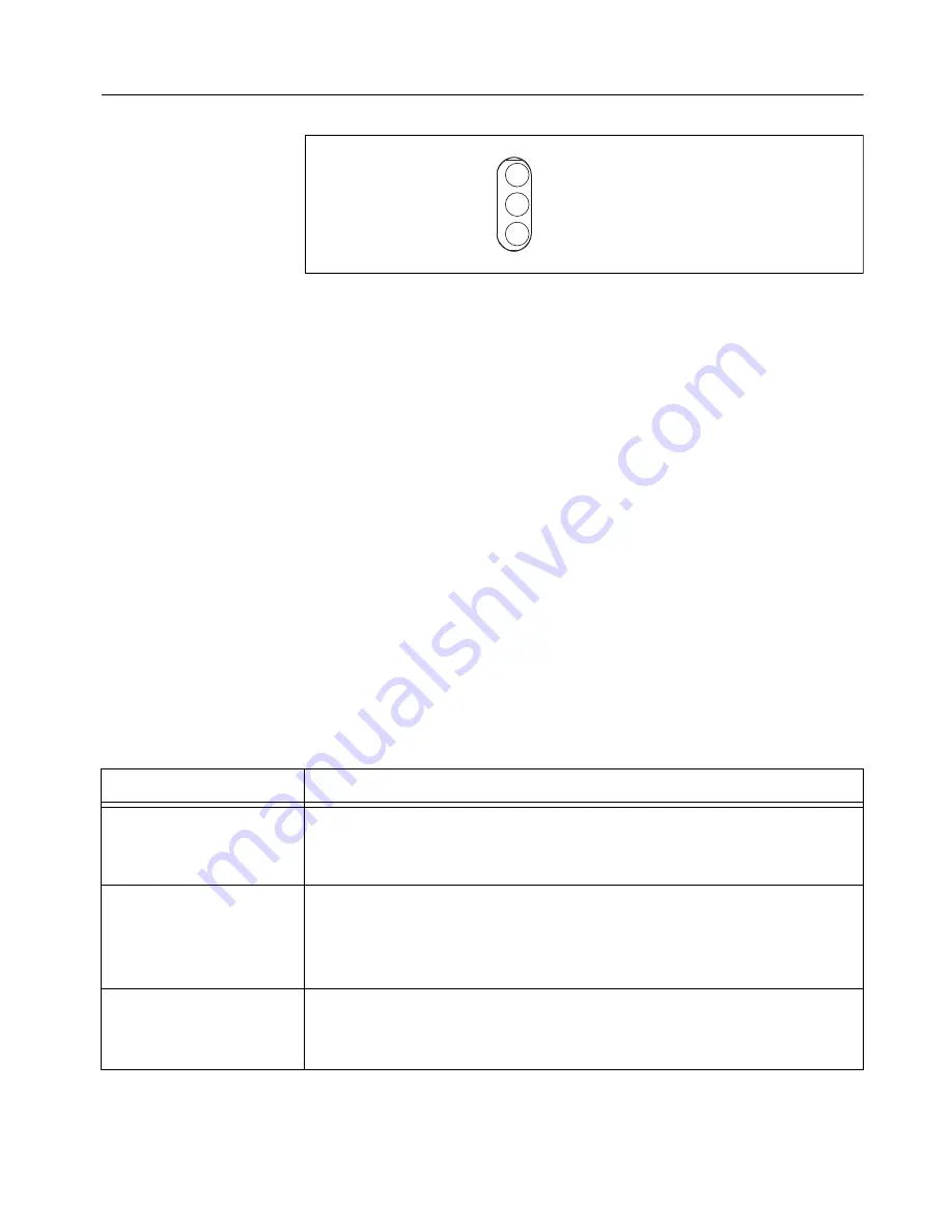
Figure 13.
NI 9148 LEDs
POWER LED
The POWER
LED is lit while the NI 9148
is powered on. This LED
indicates that the power supply connected to the chassis
is adequate.
USER FPGA1 LED
You can use the USER FPGA LED to help debug your application or easily
retrieve application status. Use the LabVIEW FPGA Module and NI-RIO
software to define the USER FPGA1 LED to meet the needs of your
application. Refer to
LabVIEW Help
for information about programming
this LED.
STATUS LED
The STATUS LED is off during normal operation. The NI 9148
indicates
specific error conditions by flashing the STATUS LED a certain number of
times every few seconds, as shown in Table 2.
Table 2.
Status LED Indications
Number of Flashes
Indication
1
The chassis is unconfigured. Use MAX to configure the chassis. Refer
to the
Measurement & Automation Explorer Help
for information about
configuring the chassis.
2
The chassis
has detected an error in its software. This usually occurs
when an attempt to upgrade the software is interrupted. Reinstall
software on the chassis. Refer to the
Measurement & Automation
Explorer Help
for information about installing software on the chassis.
3
The chassis is in safe mode because the SAFE MODE DIP switch is in
the ON position. Refer to the
Configuring DIP Switches
section for
information about the SAFE MODE DIP switch.
POWER
USER FPGA1
STATUS


