


NI 9148 Operating Instructions and Specifications
10
ni.com
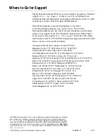
The NI 9148 has one layer of reverse-voltage protection. Complete the
following steps to connect a power supply to the chassis.
1.
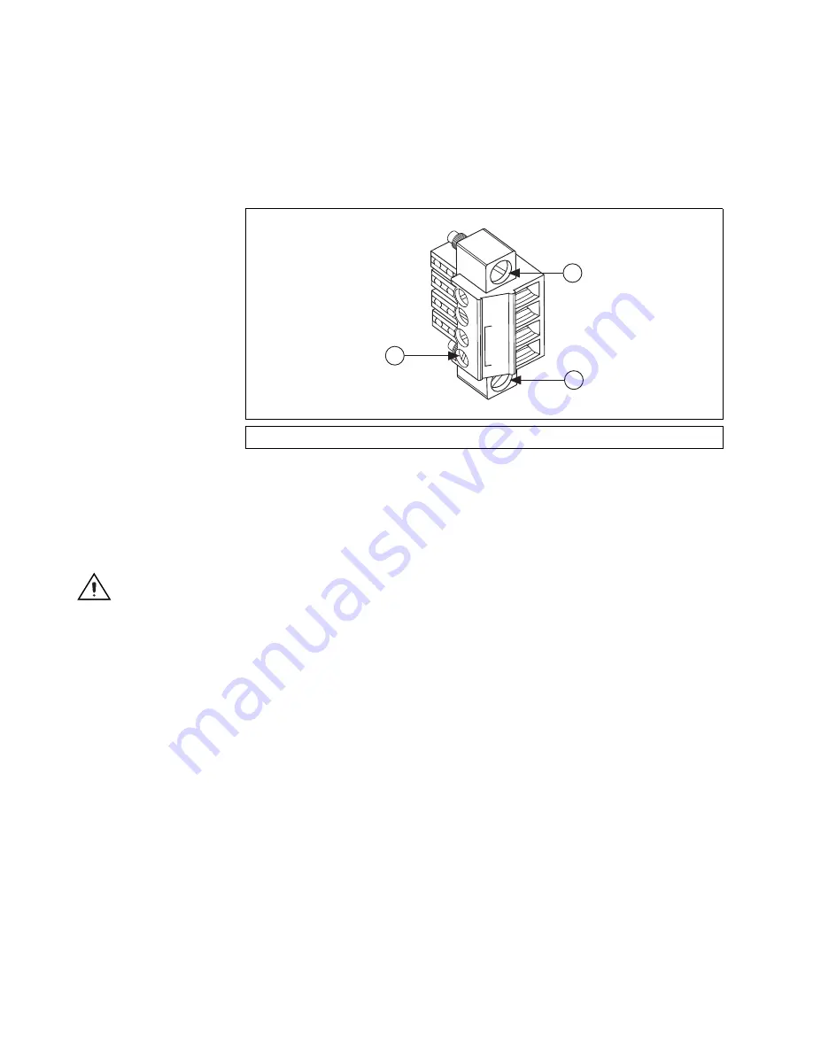
Connect the positive lead of the power supply to the V terminal of the
COMBICON connector shipped with the NI 9148, and tighten the
terminal screw. Figure 11 shows the terminal screws, which secure the
wires in the screw terminals, and the connector screws, which secure
the power connector on the controller.
Figure 11.
COMBICON Power Connector
2.
Connect the negative lead of the power supply to one of the C terminals
of the COMBICON connector.
3.
Install the COMBICON connector on the front panel of the NI 9148.
Caution
The C terminals are internally connected to each other.
Powering On the NI 9148
When you apply power to the NI 9148, the chassis runs a power-on self test
(POST). During the POST, the Power and Status LEDs turn on. The Status
LED turns off, indicating that the POST is complete. If the LEDs do not
behave in this way when the system powers on, refer to the
Understanding
LED Indications
section.
Chassis Startup Options
Table 1 lists the startup options available for the NI 9148. These options
determine how the chassis behaves when it starts up in various conditions.
Use the RIO Device Setup utility to select startup options. Access the
RIO Device Setup utility by selecting
Start»All Programs»National
Instruments»NI-RIO»RIO Device Setup
.
1
Termin
a
l Screws
2
Connector Screws
C
NC
C
V
2
1
2


