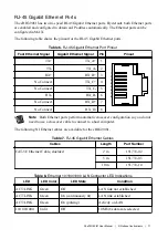
Table 8.
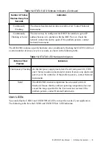
Ethernet 10/100/1000 LAN Connector LED Indications (Continued)
LED
LED Color
LED State
Condition
10/100/1000
Green
On
100 Mbit/s data rate selected
10/100/1000
Yellow
On
1,000 Mbit/s data rate selected
CPU eXpansion Module (CXM) Connector
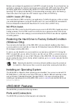
In the future, the CXM connector will enable you to connect additional industry-standard I/O
to the cRIO-9081.
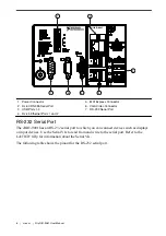
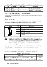
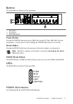
Power Connector
The cRIO-9081 has a power connector to which you can connect a primary and secondary
power supply. The following table shows the pinout for the power connector.
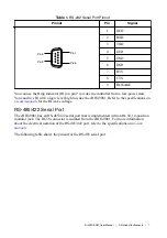
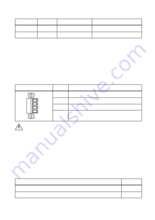
Table 9.
Power Connector Pinout
Pinout
Pin
Description
V1
C
V2
C
V1
Primary power input
C
Common
V2
Secondary power input
C
Common
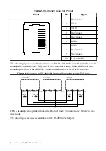
Caution
The C terminals are internally connected to each other, but are not
connected to chassis ground. This isolation is intended to prevent ground loops and
does not meet UL ratings for safety isolation. You can connect the C terminals to
chassis ground externally. Refer to the specifications on
for
information about the power supply input range and maximum voltage from
terminal to chassis ground.
If you apply power to both the V1 and V2 inputs, the cRIO-9081 operates from the V1 input.
If the input voltage to V1 is insufficient, the cRIO-9081 operates from the V2 input.
The cRIO-9081 has reverse-voltage protection.
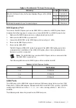
The following NI power supplies and accessories are available for the cRIO-9081.
Table 10.
Power Accessories
Accessory
Part Number
NI PS-15 Power Supply, 24 VDC, 5 A, 100-120/200-240 VAC Input
781093-01
NI PS-10 Desktop Power Supply, 24 VDC, 5 A, 100-120/200-240 VAC Input 782698-01
12
|
ni.com
|
NI cRIO-9081 User Manual


