Advantech IPC-7132 Скачать руководство пользователя страница 1

User Manual

IPC-7132

Cost-effective Desktop / Wallmount 
Chassis for ATX/Micro ATX 
Motherboard and 10 Slot Backplane

用于 ATX/Micro ATX 主板和 10 槽底板的
直立式 / 壁挂式机箱
用於 ATX/Micro ATX 主板和 10 槽底板的
直立式 / 壁掛式機箱

Содержание IPC-7132

Страница 1: ...User Manual IPC 7132 Cost effective Desktop Wallmount Chassis for ATX Micro ATX Motherboard and 10 Slot Backplane ATX Micro ATX 10 ATX Micro ATX 10...

Страница 2: ...d assumes no responsibility for its use nor for any infringe ments of the rights of third parties which may result from its use 2012 2012 Acknowledgements IPC 7132 AIMB 763 AIMB 766 AIMB 767 AIMB 769...

Страница 3: ...All cautions and warnings on the equipment should be noted 12 If the equipment is not used for a long time disconnect it from the power source to avoid damage by transient overvoltage 13 Never pour an...

Страница 4: ...nents can be damaged by sudden power surges 20 CAUTION Always ground yourself to remove any static charge before touching the motherboard backplane or add on cards Modern electronic devices are very s...

Страница 5: ...v IPC 7132 User Manual 1 AEL 1 1 1M 18 FCC 15 1 2 19 20 21 22 CCC CLASS I LASER PRODUCT KLASS I LASER PRODUKT...

Страница 6: ...IPC 7132 User Manual vi 1 2 3 4 5 6 7 0 C 32 F 40 C 104 F 8 9 10 11 12 13 14 15 16 17 IEC 60825 18 FCC 15 1 2 19 20 21 CLASS I LASER PRODUCT KLASS I LASER PRODUKT...

Страница 7: ...best performance possible from your products If you run into technical difficulties we are here to help For the most frequently asked questions you can easily find answers in your product documentati...

Страница 8: ...ials service time and freight Please consult your dealer for more details If you think you have a defective product follow these steps 1 Collect all the information about the problem encountered For e...

Страница 9: ...sales repre sentative immediately We have carefully inspected the IPC 7132 mechanically and electrically before shipment It should be free of marks and scratches and in perfect working order upon rece...

Страница 10: ...IPC 7132 User Manual x IPC 7132 CPU IPC 7132 IPC 7132...

Страница 11: ...ternal 3 5 HDD 5 25 ODD into Drive Bay 3 5 5 25 HDD 6 Figure 2 2 Installing Internal 3 5 HDD 5 25 ODD into Drive Bay 3 5 5 25 HDD 6 2 3 Installing the Motherboard Add On Card 7 Figure 2 3 Installing t...

Страница 12: ...st 14 Figure A 1 Exploded Diagram 14 Table A 1 Table A 1 Part List 14 Appendix B Motherboard Options 15 B 1 Motherboard Options 16 Table B 1 ATX motherboard options ATX ATX 16 Table B 2 MicroATX mothe...

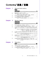
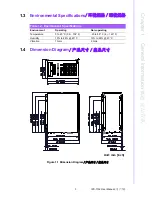
Страница 13: ...Chapter 1 1 General Information...

Страница 14: ...330 H x 430 D mm 3 3 5 HDD 1 5 25 HDD 2 2 5 HDD LED LED HDD 1 x 12 cm 85 CFM 9 96 kg 21 93 lb 200 W x 330 H x 430 D mm 3 3 5 HDD 1 5 25 HDD 2 2 5 HDDs LED LED HDD 1 x 12 cm 85 CFM 9 96 kg 21 93 lb 200...

Страница 15: ...ntal Specifications 1 4 Dimension Diagram Figure 1 1 Dimension Diagram Table 1 2 Environment Specifications Environment Operating Non operating Temperature 0 to 40 C 32 104 F 20 to 60 C 4 140 F Humidi...

Страница 16: ...IPC 7132 User Manual 4...

Страница 17: ...Chapter 2 2 System Setup...

Страница 18: ...er Manual 6 2 1 Removing Side Cover Figure 2 1 Removing Side Cover 2 2 Installing Internal 3 5 HDD 5 25 ODD into Drive Bay 3 5 5 25 HDD Figure 2 2 Installing Internal 3 5 HDD 5 25 ODD into Drive Bay 3...

Страница 19: ...er 2 System Setup 2 3 Installing the Motherboard Add On Card Figure 2 3 Installing the Motherboard Add On Card 2 4 Installing Drive Bay into IPC 7132 IPC 7132 IPC 7132 Figure 2 4 Install Drive Bay int...

Страница 20: ...IPC 7132 User Manual 8 2 5 Installing Wallmount Bracket Figure 2 5 Installing Wallmount Bracket Unit mm inch...

Страница 21: ...9 IPC 7132 User Manual Chapter 2 System Setup Note This pair of wallmount bracket is designed for side of chassis and bot tom side Reverse installation is not permitted...

Страница 22: ...IPC 7132 User Manual 10...

Страница 23: ...Chapter 3 3 Operation...

Страница 24: ...IPC 7132 User Manual 12 3 1 Cleaning the Filter Figure 3 1 Cleaning the Filter 3 2 Changing Power Supply Figure 3 2 Changing Power Supply...

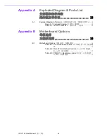
Страница 25: ...Appendix A A Exploded Diagram Parts List...

Страница 26: ...BRACKET 2 I O PANEL 13 SWITCH BRACKET 3 SIDE COVER 14 RESET SWITCH 4 ODD BRACKET 15 POWER SWITCH 5 HDD BRACKET 16 USB CABLE 6 HOLD DOWN CLAMP 17 POWER LED CABLE 7 FAN BRACKET 18 HDD LED CABLE 8 FAN F...

Страница 27: ...Appendix B B Motherboard Options...

Страница 28: ...PC 7132 ATX MicroATX 10 IPC 7132 ATX MicroATX 10 Table B 1 ATX motherboard options ATX ATX Model Name Bus PCI PCI ISA ISA SATA AIMB 781 1 PCIe x16 Gen2 1 PCIe x4 1 PCIe x1 4 PCI 32 bit 6 AIMB 780 1 PC...

Страница 29: ...1 PCIe x4 2 PCI 32 bit 6 AIMB 567 1 PCIe x16 1 PCIe x4 1 PCIe x1 2 PCI 32 bit 4 AIMB 566 1 PCIe x4 1 PCI 32 bit 6 AIMB 564 1 PCIe x16 1 PCIe x4 2 PCI 32 bit 7 AIMB 562 1 PCIe x1 2 PCI 32 bit 2 Table B...

Страница 30: ...e No part of this publication may be reproduced in any form or by any means electronic photocopying recording or otherwise without prior written permis sion of the publisher All brand and product name...

Отзывы: