


EN
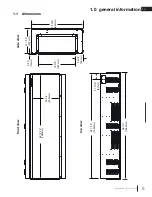
17
electrical information
W415-4188 / B-0 / 11.13.23
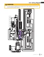
3.2 240V hard wiring
3.3 wall mount controller installation
1. Insert Green or bare copper wire to the designated G Terminal. Tighten the screw.
2. Insert Neutral wire to the designated N Terminal. Tighten the screw.
3. Insert L1 wire to the designated L1 Terminal. Tighten the screw.
4. Insert L2 wire to the designated L2 Terminal. Tighten the screw.
note:
If installing with the optional wall mount controller, plug in the wire harness connection to the 4 pin
connector located to the left of the hard wire terminal block.
5. Make sure all connections are tightened properly.
6. Reinstall the junction box cover plate.
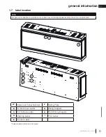
This is an optional accessory controller. See installation instructions for the wall mount controller.
FIREPLACE JUNCTION
JONCTION DE L'APP
AREIL
POWER SUPPL
Y
SOURCE D'ALIMENT
AT
IO
N
WHITE/BLANC (N)
BLACK/NOIR (L1)
RED/ROUGE (L2)
GREEN/VERT (G)
240V
BLACK/NOIR (L1)
WHITE/BLANC (N)
RED/ROUGE (L2)
GREEN/VERT (G)
G L2
L1
N
G
L1
N
L2
Содержание Luminex Series
Страница 39: ...EN 39 notes W415 4188 B 0 11 13 23...
Страница 79: ...79 notes W415 4188 B 0 11 13 23 FR...


