background image

9

W415-0153 / A / 10.29.01

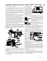
VERTICAL VENTING INSTALLATION

1. 

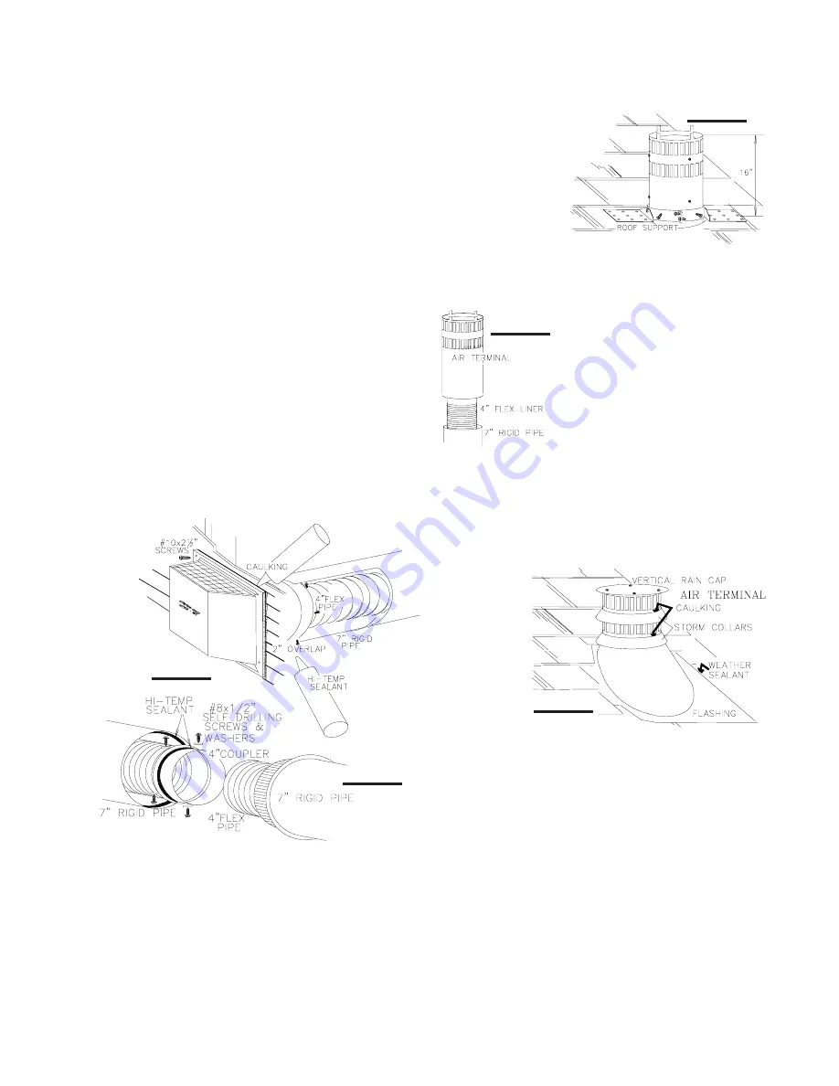
Fasten the roof

support to the roof us-
ing the screws pro-
vided. The roof support
is optional. In this case
the venting is to be ad-
equately supported
using either an alter-
nate method suitable
to the authority having
jurisdiction or the op-
tional roof support.

2. 

Slip a 4" diameter length of aluminium flexible liner a

minimum of 2" over the inner sleeve of the air terminal.

Secure to the sleeve using 3 screws
and flat washers. Seal the joint and
screw heads using high temperature
sealant. Repeat using a 7" diameter
length of rigid piping.

If the attic space is tight, we rec-
ommend adding sufficient lengths
of 7" rigid piping, secured and
sealed as necessary.

3.

 Thread the air terminal pipe assembly down through

the roof  support and attach, ensuring that a minimum 16"
of air terminal will penetrate the roof when fastened. The
air terminal must be located vertically and plumb.

4.

 Remove nails from the shingles, above and to the

sides of the chimney. Place the flashing over the air termi-
nal and slide it underneath the sides and upper edge of
the shingles. Ensure that the air terminal is properly
c e n t e r e d
within the
flashing, giv-
ing a 3/4"
margin all
around. Fas-
ten to the roof.
Do 

NOT

 nail

through the
lower portion
of the flash-
ing. Make weather-tight by sealing with caulking. Where
possible, cover the sides and top edges of the flashing
with roofing material.

5. 

Apply a heavy bead of waterproof caulking 2 inches

above the flashing. Slide the storm collar around the air
terminal and down to the caulking. Tighten to ensure that a
weather-tight seal between the air terminal and the collar
is achieved. Attach the other storm collar centered between
the air intake and air exhaust slots onto the air terminal.
Tighten securely.

6. 

Attach the vertical rain cap.

7. 

In the attic, slide the vent pipe collar down to cover up

the open end of the shield and tighten. This will prevent any
materials, such as insulation, from filling up the 1" air space
around the pipe. 

Figure 15.

HORIZONTAL VENTING INSTALLATION

For safe and proper operation of the stove, follow the
venting instructions exactly.
For horizontal runs, both Wolf Steel and Simpson Dura-
vent venting components may have a 0" rise per foot.
For optimum performance it is recommended that all
horizontal runs have a minimum ¼ inch rise per foot.

1. 

Stretch the 4" diameter aluminium flexible liner to the

required length taking into account the additional length
needed for the finished wall surface.

Spacers are attached to the 4" inner flex liner at predeter-
mined intervals to maintain a 1-1/4" air gap to the 7" outer
stove pipe. These spacers must not be removed.


Slip a 4" diameter length of aluminium flexible liner a mini-

mum of 2" over the inner sleeve of the air terminal. Secure
to the sleeve using 3 screws. Seal the joint and screw
heads using the high temperature sealant provided.

2.

 Slip the first section of  7" diameter stove pipe a mini-

mum of  2" over the outer sleeve of the air terminal

.

 Secure

to the sleeve using 3 screws. Seal the joint and screw
heads using high temperature sealant.

3. 

Insert the liners through the firestop / vent pipe shield.

Holding the air terminal (lettering in an upright, readable
position), secure to the exterior wall. Make weather tight by
sealing with caulking (not supplied). The air terminal mount-
ing plate may be recessed (up to 

3

/

4

" maximum) into the

exterior wall or siding.

4. 

If more than one length of liner needs to be used to

reach the stove, couple them together as illustrated in

FIGURE 17

. Seal the joints using the same procedure as

described above.

The vent system must be supported approximately every
10 feet along a horizontal run. Use supports or equivalent
non-combustible strapping to maintain the 1" clearance
from combustibles.

FIGURE 16

FIGURE 17

FIGURE 18

FIGURE 19

FIGURE 20

Содержание Haliburton GDS28N

Страница 1: ...ada L4M 4Y8 705 721 1212 R 2000 Installation and service must be performed by a qualified installer service agency or the gas supplier WARNING If the information in these instructions is not followed...

Страница 2: ...uld stay away to avoid burns or clothing ignition Supervise young children when they are in the same room as the stove Due to high temperatures the stove should be located out of traffic and away from...

Страница 3: ...Labour costs to the however requires the prior approval of an authorized company official Labour costs to the account of account of account of account of account of NAPOLEON NAPOLEON NAPOLEON NAPOLEON...

Страница 4: ...aler Do not substitute materials Clean the glass after the first 10 hours of operation with a recommended gas fireplace glass cleaner Thereafter clean as required Do not clean glass when hot If the gl...

Страница 5: ...VENTING LENGTHS AND AIR TERMI NAL LOCATIONS Use only Wolf Steel or Simpson Dura Vent Model DV GS venting components Minimum and maximum vent lengths for both horizontal and vertical installations and...

Страница 6: ...d OFFSET INSTALLATION EXAMPLE FIGS 5 FIGURE4 If a first run of 72 inches is re quired using the First Vent Run on the chart shows that a maxi mum second run of 48 inches is allowable IF NECESSARY THE...

Страница 7: ...EET Clearance above grade veranda porch deck or balcony Clearance to windows or doors that open Clearance to permanently closed windows Vertical clearance to ventilated soffit located above the termin...

Страница 8: ...sition apply sealant between the pipe and the firestop spacer 3 In the attic after the pipe has been installed slide the vent pipe collar down to cover up the open end of the shield and tighten This w...

Страница 9: ...rain cap 7 In the attic slide the vent pipe collar down to cover up the open end of the shield and tighten This will prevent any materials such as insulation from filling up the 1 air space around the...

Страница 10: ...e base For mobile home installations the fireplace must be fastened in place Use 10 screws inserted through the holes in the base to se cure It is recommended that the fireplace be secured in all inst...

Страница 11: ...ew the wire access cover plate from the rear right hand side of the firebox Remove and discard the gasket SEE FIGURE 25 Remove the knockout from the cover plate and insert the protective bushing Pull...

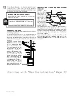
Страница 12: ...of or building within 10 feet FIGURE 26 This is a guideline only local venting codes should be followed which may differ in height and clearance requirements Continue with Gas Installation Page 13 INS...

Страница 13: ...IES TO CANADA ONLY L EFFICACITE CONSTANTE S APPLIQUENT SEULEMENT AU CANADA AFUE NG LP GN GP 64 65 MINIMUM AND MAXIMUM HORIZONTAL VENT LENGTHS ARE 25 INCHES AND 20 FEET RESPECTIVELY LES LONGUEURS HORIZ...

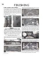
Страница 14: ...close to the firebox wall as possible and centered onto the log support pan FIGURES 31 FIGURES 30 Place the front log on the ember screen lining up the studs with the holes on the bottom of the log CA...

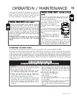
Страница 15: ...n MODEL GS28 ONLY SPILL SWITCH This is a thermally activated switch attached to the back of the chimney adapter which senses the change in temperature and shuts down the gas valve in the event of a se...

Страница 16: ...servicing the stove CAUTION Label all wires prior to disconnection when serv icing controls Wiring errors can cause improper and dan gerous operation Verify proper operation after servicing This stove...

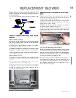
Страница 17: ...neither pinched nor interfere with the blower operation Re se cure the air intake manifolds INSTALLATION THROUGH THE FIRE BOX Replacement blower access gasket is required 2 Open the lower control door...

Страница 18: ...el plate To access the venturi remove the air housing cover plate held on with 2 screws Take care not to damage the gasket Natural gas and propane models have air shutters set fully open Closing the a...

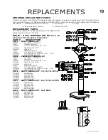
Страница 19: ...ABLE PIPE 7 DIA W500 0077 FIRESTOP WALL PLATE W020 0032 HARDWARE BRTC7 BRASS TRIM COLLAR BM6724 24 STOVE PIPE 7 DIAMETER W010 0300 10 ALUMINIUM FLEX LINER C W SPACERS 4 DIA W025 0001 DECORATIVE BRASS...

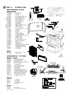
Страница 20: ...ARIABLE SPEED SWITCH GZ 552 REPLACEMENT BLOWER W030 0022 ACCENT BAR W200 0077 BLACK TRIVET GS28 W010 0459 ADAPTOR C W SPILL SWITCH W660 0006 SPILL SWITCH ACCESSORIES OPTIONS GDS28 GS28 W690 0001 MILLI...

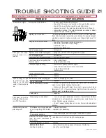
Страница 21: ...standing Main burner is in OFF position turn on all gas appliances and see if pilot flame flutters diminishes or extinguishes especially when main burner ig nites Monitor supply pressure check if supp...

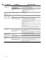
Страница 22: ...location of storm collars Incorrect installation Carbon is being de posited on glass logs or combustion chamber surfaces Flame is impinging on the logs or combustion chamber check that the logs are co...

Страница 23: ...23 W415 0153 A 10 29 01 Wolf Steel Fireplace Service History This fireplace must be serviced annually depending on usage Date Service Technician Name Service Performed Special Concerns Dealer Name...

Страница 24: ...24 W415 0153 A 10 29 01 NOTES...

Отзывы: