12
W415-0153 / A / 10.29.01
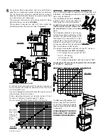
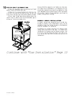
For aesthetics, the adapter has been designed to accept
a standard matte black 7" stove pipe and the Napoleon
decorative brass band (standard with the GS-150KT). Both
are available from your Napoleon dealer.
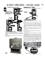
B-VENT MODEL GS28 ONLY:
Attach the B-Vent label, shown below, in the control
area of the appliance.
COMBUSTION AIR
A chimney venting this stove shall not vent any solid
fuel burning appliance.
For optimum performance it is recommended that all
horizontal runs have a minimum ¼ inch rise per foot.
Any stove needs air for safe operation and must be
installed in such a way that adequate combustion air is
available.
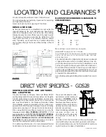
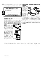
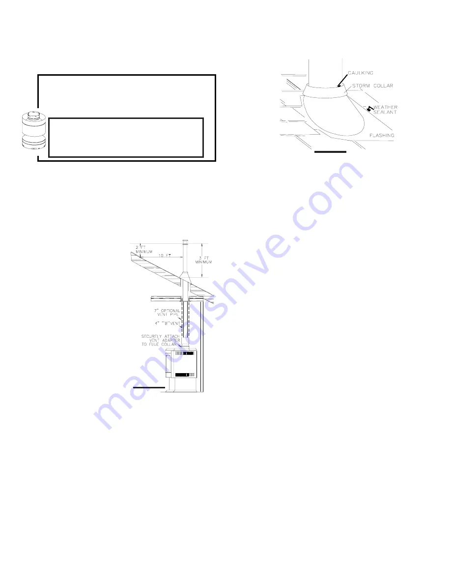
ADDING VENT SEC-
TIONS:
For ease of assem-
bly, a 7" telescoping stove
pipe may be installed over the
4" vent connection of the
adapter. Add vent sections,
twist locking (clockwise) se-
curely, to the required height.
The vent should extend, at
least, 3 feet above its point of
contact with the roof and, at
least, 2 feet higher than any
wall, roof or building within 10
feet.
FIGURE 26.
(This is a
guideline only; local venting
codes should be followed
which may differ in height and
clearance requirements.)
Continue with "Gas Installation" Page 13
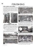
INSTALLING FLASHING AND STORM
COLLAR
Remove nails
from the shingles
above and to the
sides of the chim-
ney. Place the
flashing over the
vent pipe and
slide it under-
neath the sides
and upper edge
of the shingles.
Ensure that the
vent pipe is properly centered within the flashing, giving a
3/4" margin all around. Fasten to the roof on the top and
sides. DO NOT NAIL through the lower portion of the flash-
ing. Make weather-tight by sealing with caulking. Where
possible, cover the sides and top edges of the flashing
with roofing material.
Apply waterproof caulking around the vent, 1" above the
top of the flashing and push the storm collar down into the
caulking.
FIGURE 27.
Attach a rain cap to the top of the last
vent section.
FIGURE 26
FIGURE 27
ATTACH THIS LABEL IN THE CONTROL AREA OF THE FIREPLACE.
THIS FIREPLACE HAS BEEN CONVERTED TO A ‘B’VENT MODEL.
ATTACHEZ CET ETIQUETTE DANS LA REGION DE CONTROLE DU FOYER.
CE FOYER A ETE CONVERTI A UN MODELE A SYSTEME D’EVACUATION ‘B’.
Содержание Haliburton GDS28N
Страница 24: ...24 W415 0153 A 10 29 01 NOTES...

