13
W415-0153 / A / 10.29.01
Mark the appropriate boxes
on the rating plate label to indi-
cate the model type depending on the installation (direct
vent or B-vent).
Read the section on opening the door in "Finishing" prior
to proceeding to prevent damaging the unit.
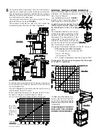
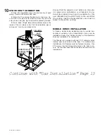
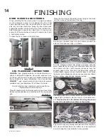
Bring the gas line to the stove through either the opening
in the pedestal back or through the floor directly beneath
the pedestal base.
Install rigid black pipe, or 1/2" type L copper tubing with a
shutoff valve to the stove.
Seal and tighten the gas line securely to the flex connector
supplied.
DO NOT KINK FLEXIBLE CONNECTOR.
MODEL GDS28 ONLY:
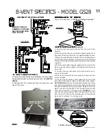
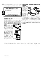
Attach the two leads from the on/
off switch to terminals 1 and 3 located on the gas valve.
Do not connect either the wall switch, thermostat or
gas valve to electricity (110 volts).
FIGURE 28
O L
OT
PIL
L
O
T
IH
N
O
P
O
I
FF
FIGURE 29
GAS INSTALLATION
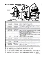
Check for gas leaks by brushing on a soap and water solu-
tion.
DO NOT USE OPEN FLAME.
For ease of accessibility, an optional remote wall switch
or millivolt thermostat may be installed in a convenient
location. Route a double strand of solid core millivolt
wire from the gas stove to the wall switch / millivolt ther-
mostat. The recommended maximum lead length de-
pends on the wire size:
WIRE SIZE
MAX. LENGTH
14 gauge
100 feet
16 gauge
60 feet
18 gauge
40 feet
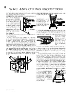
DIRECT VENT MODEL GDS28:
Disconnect the exist-
ing wires from terminals 1 and 3 (from the on/off switch)
and replace with the leads from the wall switch/millivolt
thermostat.
B-VENT MODEL GS28:
Disconnect the on/off switch wire
from terminal 3 on the valve and the second switch wire
from the terminal block. Replace each connection using
the wires from the wall switch/millivolt thermostat.
SERIAL NUMBER
NO. DE SERIE
MODEL CDVS280/GDS28
APPROVED FOR BEDROOM, BATH-
ROOM & BEDSITTING ROOM INSTALLATION. SUITABLE FOR
MOBILE HOME INSTALLATION IF INSTALLED IN ACCORDANCE
WITH THE CURRENT STANDARD CAN/CSA Z240MH SERIES
GAS EQUIPPED MOBILE HOMES, IN CANADA OR IN THE
UNITED STATES THE MANUFACTURED HOME
CONTRUCTION AND SAFETY STANDARD, TITLE 24 CFR,
PART 3280. WHEN THIS US STANDARD IS NOT APPLICABLE
USE THE STANDARD FOR FIRE SAFETY CRITERIA FOR MANU-
FACTURED HOME INSTALLATIONS, SITES AND COMMUNI-
TIES, ANSI / NFPA 501A.
HOMOLOGUE POUR INSTALLATION DANS UNE CHAMBRE A
COUCHER, UNE SALLE DE BAIN ET UN STUDIO. APPROPRIE
POUR INSTALLATION DANS UNE MAISON MOBILE SI SON IN-
STALLATION CONFORME AUX EXIGENCES DE LA NORME
CAN/CSA Z240MH SERIE DE MAISONS MOBILES EQUIPEES AU
GAZ, EN VIGUEUR AU CANADA OU AUX ETATS-UNIS DE LA
NORME DE SECURITE ET DE CONSTRUCTION DE MAISONS
MANUFACTUREES, TITRE 24 CFR, SECTION 3280. DANS LE
CAS OU CETTE NORME D'ETATS-UNIS NE PEUT ETRE
APPLIQUEE, SE REFERER A LA NORME RELATIVE AU CRITERE
DE MESURES DE SECURITE CONTRE L'INCENDIE POUR LES
INSTALLATIONS DANS LES MAISONS MANUFACTURES, LES
SITES ET LES COMMUNAUTES, ANSI/NFPA 501A.
STEADY STATE EFFICIENCY (NG):
75% FAN OFF / 78% FAN ON
STEADY STATE EFFICIENCY (LP):
75% FAN OFF / 79% FAN ON
EFFICACITE CONSTANTE (GN):
75% VENT. ARRETE
78% VENT. FONCTIONNE
EFFICACITE CONSTANTE (GP):
75% VENTILATEUR ARRETE
79% VENTILATEUR FONCTIONNE
STEADY STATE EFFICIENCY APPLIES TO CANADA ONLY /
L'EFFICACITE CONSTANTE S'APPLIQUENT SEULEMENT AU
CANADA.
AFUE (NG/LP) (GN/GP):
64% / 65%
MINIMUM AND MAXIMUM HORIZONTAL VENT LENGTHS ARE
25 INCHES AND 20 FEET RESPECTIVELY. LES LONGUEURS
HORIZONTALES MINIMALE ET MAXIMALE SONT 25 POUCES
ET 20 PIEDS RESPECTIVEMENT.
THE APPLIANCE MUST BE VENTED USING THE APPROPRI-
ATE NAPOLEON VENT KITS. SEE OWNERS INSTALLATION
MANUAL FOR VENTING SPECIFICS. PROPER REINSTALLA-
TION AND RESEALING IS NECESSARY AFTER SERVICING THE
VENT-AIR INTAKE SYSTEM.
L'APPAREIL DOIT EVACUER SES GAZ EN UTILISANT
L'ENSEMBLE D'EVACUATION PROPRE A NAPOLEON.
REFERER AU MANUEL D'INSTALLATION DE PROPRIETAIRE
POUR L'EVACUATION PRECISE. IL EST IMPORTANT DE BIEN
REINSTALLER ET RESCELLER L'EVENT APRES AVOIR AS-
SURE LE MAINTIEN DU SYSTEME DE PRISE D'AIR.
MANIFOLD PRESSURE:
3.5 INCHES W.C. (NG) / 10 INCHES
W.C.(LP)
PRESSION AU COLLECTEUR:
3.5" D'UNE COLONNE
D'EAU(GN)
10" D'UNE COLONNE D'EAU (PG)
MIN SUPPLY PRESSURE:
4.5" W.C.(NG) / 11" W.C. (LP)
PRESSION D'ALIMENTATION MIN:
4.5" D'UNE COLONNE D'EAU
(GN)
11" D'UNE COLONNE D'EAU (PG)
MAX. SUPPLY PRESSURE:
7" W.C. (NG) / 13" W.C. (LP)
PRESSION D'ALIMENTATION MAX:
7" D'UNE COLONNE D'EAU
(GN)
13" D'UNE COLONNE D'EAU (PG)
FOR USE WITH GLASS DOORS CERTIFIED WITH THIS UNIT
ONLY.
UTILISER AVEC LES PORTES VITREES HOMOLOGUEES
SEULEMENT AVEC CETTE UNITE.
WARNING:
DO NOT ADD ANY MATERIAL TO THE APPLIANCE,
WHICH WILL COME IN CONTACT WITH THE FLAMES, OTHER
THAN THAT SUPPLIED BY THE MANUFACTURER WITH THE AP-
PLIANCE.
AVERTISSEMENT:
N'AJOUTEZ PAS A CET APPAREIL
AUCUN MATERIAU DEVANT ENTRER EN CONTACT
AVEC LES FLAMMES AUTRE QUE CELUI QUI EST FOURNI
AVEC CET APPAREIL PAR LE FABRICANT.
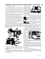
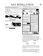
MINIMUM CLEARANCE TO COMBUSTIBLE MATERIAL /
DEGAGEMENTS MINIMAUX DES MATERIAUX COMBUSTIBLES:
A
7"
D
17½"
B
2"
E
6¼"
C
1"
F
9½"
20" TO CEILING FROM STOVE TOP
20" ENTRE LE DESSUS DU FOYER ET LE PLAFOND
ELECTRICAL RATING / CLASS.:
115V 1.5AMP 60HZ
MODEL CS280/GS28
APPROVED FOR BEDROOM, &
BEDSITTING ROOM INSTALLATION. HOMOLOGUE POUR IN-
STALLATION DANS UNE CHAMBRE A COUCHER, & UN
STUDIO.
STEADY STATE EFFICIENCY (NG):
80% FAN OFF / 82%
FAN ON
STEADY STATE EFFICIENCY (LP):
80% FAN OFF / 83%
FAN ON
EFFICACITE CONSTANTE (GN):
80% VENT. ARRETE
82% VENT. FONCTIONNE
EFFICACITE CONSTANTE (GP):
80% VENTILATEUR ARRETE
83% VENTILATEUR FONCTIONNE
STEADY STATE EFFICIENCY APPLIES TO CANADA ONLY /
L'EFFICACITE CONSTANTE S'APPLIQUENT SEULEMENT AU
CANADA.
AFUE (NG/LP) (GN/GP):
66% / 68%
THIS APPLIANCE MUST BE INSTALLED USING AN ADAPTER
KIT GS-150KT. CET APPAREIL DOIT ETRE INSTALLE EN UTILI-
SANT UN ENSEMBLE ADAPTATEUR GS-150KT.
NOT FOR USE WITH SOLID FUEL
UN COMBUSTIBLE SOLIDE NE DOIT PAS ETRE UTILISE
AVEC CET APPAREIL
WOLF STEEL LTD
BARRIE, ONTARIO CANADA
MADE IN CANADA / FABRIQUE AU CANADA
WS-385-165
GDS28
CERTIFIED
UNDER
: C
SA
2.33
A
-M98, ANSI Z21.88
A
-1998
VENTED
GAS
FIREPLACE
HEATER
.
APPLIANCE
MUST
BE
INSTALLED
USING
BURNER
KIT
:
GDS
28
BN
-
KT
,
OR
GDS
28
BP
-
KT
.
HOMOLOGUE
SELON
LES
NORMES
: C
SA
2.33
A
-M98, ANSI Z21.88
A
-1998
FOYER
DE
CHAUFFAGE
AU
GAZ
AVEC
EVACUA
-
TION
.
CET
APPAREIL
DOIT
ETRE
INSTALLE
EN
UTILISANT
UN
ENSEMBLE
DU
BRULEUR
:
GD
S28
BN
-
KT
,
OU
GDS
28
BP
-
KT
.
ALTITUDE / ELEVATION
INPUT / ALIMENTATION
REDUCED INPUT / ALIMENTATION REDUITE
OUTPUT (CDVS280/GDS28) RENDEMENT
OUTPUT (CS280/GS28) RENDEMENT
ORIFICE / INJECTEUR
DIRECT VENT MODEL
‘B’ VENT MODEL
0-4500ft (0-1370m)
30,000 BTU/h
18,000 BTU/h
22,500 BTU/h
24,000 BTU/h
#37
0-4500ft (0-1370m)
26,000 BTU/h
15,000 BTU/h
19,500 BTU/h
20,800 BTU/h
#53
GDS28-P
GS28-P
CDVS280-P
CS28-P
CDVS280-N
CS280-N
GDS28-N
GS28-N
Содержание Haliburton GDS28N
Страница 24: ...24 W415 0153 A 10 29 01 NOTES...

