


38
W415-0788 / 05.15.09
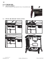
8.0 BLOWER INSTALLATION
8.0.1
Ensure that the access cover plate has been
installed. For location, see Figure 30.
8.0.2
Remove the on/off switch bracket and the
cover plate below it. The switch spacers and
cover plate may now be discarded.
8.0.3
Decide which side of the blower housing you
prefer the on/off switch to be located on.
8.0.4
Remove the 2 screws from the top outer edge
of the rear appliance panel. The housing is
mounted using these two holes, as well as two
other holes located in the rear panel. Using the
same screw holes for one side of the housing.
8.0.5
Mount and secure the blower housing using
4 screws. Ensure that the on/off switch wires
pass through the appropriate slot located on
either side of the blower housing.
8.0.6
Remove the 2 screws from the side of the
blower housing that you want the switch to be
located on and re-secure the on/off switch.
Because the blower is thermally activated,
when turned on, it will automatically start ap-
proximately 15-30 minutes after lighting the
appliance and will run for approximately 30-45
minutes after the appliance has been turned
off. Use of the fan increases the output of heat.
Drywall dust will penetrate into blower bear-
ings causing irreparable damage and must be
prevented from coming into contact with the
blower or its compartment.
Any damage resulting from this condition is not
covered by the warranty policy.
SLOT
REMOVED SCREWS
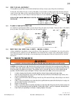
9.0 ADJUSTMENT
9.1 PILOT BURNER ADJUSTMENT
Adjust the pilot screw to provide properly sized fl ame. Turn in a
clockwise direction to reduce the gas fl ow.
Check Pressure Readings:
Inlet pressure can be checked by turning screw (A) counter-
clockwise 2 or 3 turns and then placing pressure gauge tubing over
the test point. Gauge should read 7” (minimum 4.5”) water column
for natural gas or 13” (11” minimum) water column for propane.
Check that main burner is operating on “HI”.
Outlet pressure can be checked the same as above using screw (B). Gauge should read 3.5” water column for
natural gas or 10” water column for propane. Check that main burner is operating on “HI”.
AFTER TAKING PRESSURE READINGS, BE SURE TO TURN SCREWS CLOCKWISE FIRMLY TO
RESEAL. DO NOT OVERTORQUE.
Leak test with a soap and water solution.
39.4
A
B
PILOT SCREW
NorthlineExpress.com
http://www.northlineexpress.com
Toll-Free 1-866-667-8454


