


28
W415-0788 / 05.15.09
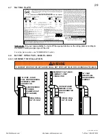
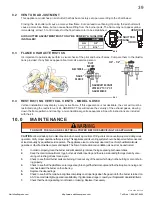
4.3 APPLIANCE VENT CONNECTION - MODEL GDS60
A.
Attach the adjustable pipe to the last section of rigid pipe.
Secure with screws and seal.
B.
Install the inner fl ex pipe to the appliance. Secure with 3 screws
and fl at washers. Seal the joint and screw holes using the high
temperature sealant W573-0007 (not supplied).
C.
Run a bead of high temperature sealant (not supplied) around
the inside of the air intake collar. Pull the adjustable pipe a
minimum 2” into the air intake collar.
NOTE: Ensure that the sealant is not visible on the exterior pipes once installation is completed. An
optional decorative black band is available for this use. In the event that the venting must be disassembled,
care must be taken to reseal the venting.
28.3
2” OVERLAP
HIGH TEMPERATURE
SEALANT
#8 X 1/2”
SELF
DRILLING
SCREWS
4.4 MOBILE HOME INSTALLATION - MODEL GDS60
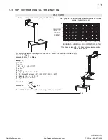
In Canada, mobile home installation may be vented horizontally or vertically. In the United States, it may only
be installed vertically. See "VERTICAL VENTING" or "HORIZONTAL AIR TERMINAL INSTALLATION" section
for installation.
For mobile home installations, the appliance must be fastened in place. It is recommended that the appliance
be secured in all installations. Use the levelling / securing kit, GDSLL-KT for this purpose.
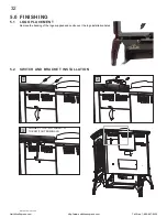
4.5 GAS
INSTALLATION
30.1
Proceed once the vent installation is complete. Installation and servicing to be done by a qualifi ed installer
Do not use open fl ame.
•
Move the appliance into position and secure.
•
If equipped with a fl ex connector the appliance is designed to accept a 1/2” gas supply. Without the
connector it is designed to accept a 3/8” gas supply. The appliance is equipped with a manual shut off
valve to turn off the gas supply to the appliance.
•
Connect the gas supply in accordance to local codes. In the absence of local codes, install to the
current CAN/CSA-B149.1 Installation Code in Canada or to the current National Fuel Gas Code, ANSI
Z223.1 / NFPA 54 in the United States.
• When
fl exing any gas line, support the gas valve so that the lines are not bent or kinked.
•
Check for gas leaks by brushing on a soap and water solution.
For ease of accessibility, an optional remote wall switch or millivolt thermostat may be installed in a convenient
location. Route 2 strand solid core millivolt wire from the gas appliance to the wall switch / millivolt thermostat.
The recommended maximum lead length depends on the wire size:
WIRE SIZE
MAX. LENGTH
14
gauge
100
feet
16
gauge
60
feet
18
gauge
40
feet
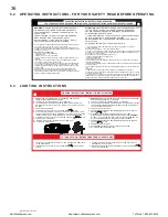
DIRECT VENT MODEL GDS60:
Disconnect one wire to the on/off switch and connect the wire from the wall
switch / millivolt thermostat / remote to the wire and the switch.
B-VENT MODEL GS60:
Disconnect the spill switch wire from the on/off switch and connect with the leads
from the wall switch / millivolt thermostat / remote to the wire and the switch.
4.5.1
4.5.2
4.5.3
4.5.4
4.5.5
4.6 OPTIONAL WALL SWITCH / THERMOSTAT
NorthlineExpress.com
http://www.northlineexpress.com
Toll-Free 1-866-667-8454


