


6
2
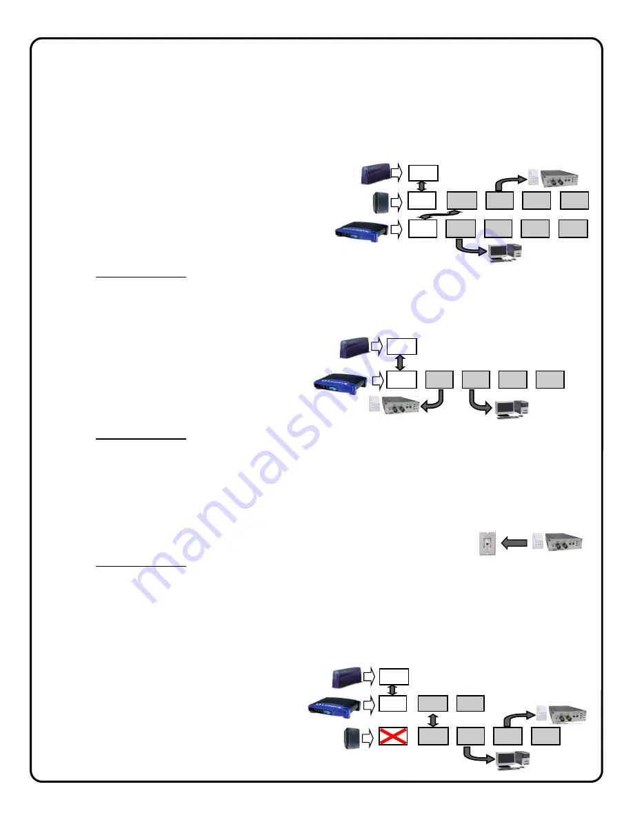
WIRE THE NETWORK CONNECTION
Cable Modem Service Installation
The use of the optional G-BOX in Cable Broadband service applications is highly recommended to provide optimum
frame rate and resolution performance. Follow the installation and connection steps below:
NOTE: If no G-BOX is available, the Cable installation may be wired in same configuration as DSL Modem, below.
1
Power down Cable Modem and Router.
2
Wire G-BOX in standard configuration as shown
(G-BOX WAN to Modem WAN).
3
Wait 15 minutes and power up Cable Modem.
4
Wait 1 minute and power up G-BOX, then Cus-
tomer’s Router.
5
Test local PC for Internet connectivity (open internet
browser and browse internet).
6
Go to www.VideoAlert.net and click NEW ACTIVATION to activate account.
Some ISP providers lock onto the MAC address of the first device after the modem. Powering down the
modem for 15 minutes will force the ISP to recognize the new MAC address of the G-BOX upon power up.
DSL Broadband Modem Installation
1
Power down DSL Modem and Router.
2
Wire as shown.
3
Wait 15 minutes and power up Modem.
4
Wait 1 minute and power up VIP Devices and
then Customer’s Router.
5
Go to www.VideoAlert.net and click NEW ACTIVATION to activate account.
ISP Type cannot be identified
In some commercial applications, it may not be possible to identify the type of ISP, or identify the modem or routers that may
be in front of the internet connection provided by the subscriber. In these cases, wire as shown below:
1
Connect the VIP devices directly into the network connection as shown (typically an network RJ45 jack connected to a
router). This corresponding port on the router must provide access to the internet.
2
Power up the VIP Device.
3
Go to www.VideoAlert.net and click NEW ACTIVATION to activate account.
This configuration will work for most commercial installations. If there is no Internet connectivity, there may be an enter-
prise class router and firewall between the network jack and the outside internet connection. This connection can be
completed by asking the IT professional to open this port to the outside world.
NOTE: If additional ports are required, the G-BOX may be used as a switch
1
Power down all devices to be connected to the G-BOX.
2
Connect the devices to the G-BOX LAN ports as
shown.
3
Power up all devices, wait one minute, power
down and then up again to ensure proper switch
operation.
BROADBAND
DSL
MODEM
WAN
(INTERNET)
CUSTOMER'S
ROUTER
CUSTOMER'S PC
AND OTHER DEVICES
WAN
LAN1 LAN2 LAN3 LAN4
VIP Devices
NETWORK
CONNECTION
VIP Devices
CUSTOMER'S
BROADBAND
DSL
MODEM
G-BOX
WAN
(INTERNET)
WAN
LAN1 LAN2 LAN3 LAN4
VIP Devices
WAN LAN1 LAN2 LAN3 LAN4
CUSTOMER’S PC AND
OTHER DEVICES
G-BOX
WAN
LAN1 LAN2 LAN3 LAN4
VIP Devices
CUSTOMER’S PC
AND OTHER DEVICES
WAN
LAN1 LAN2
BROADBAND
MODEM
WAN
(INTERNET)
CUSTOMER'S
ROUTER
Содержание iSeeVideo ISEE-SCHGW
Страница 19: ...19 NOTES...


