NAPCO iSeeVideo ISEE-SCHGW Скачать руководство пользователя страница 5


1

 INSTALL AND WIRE THE ISEE-SCHGW   


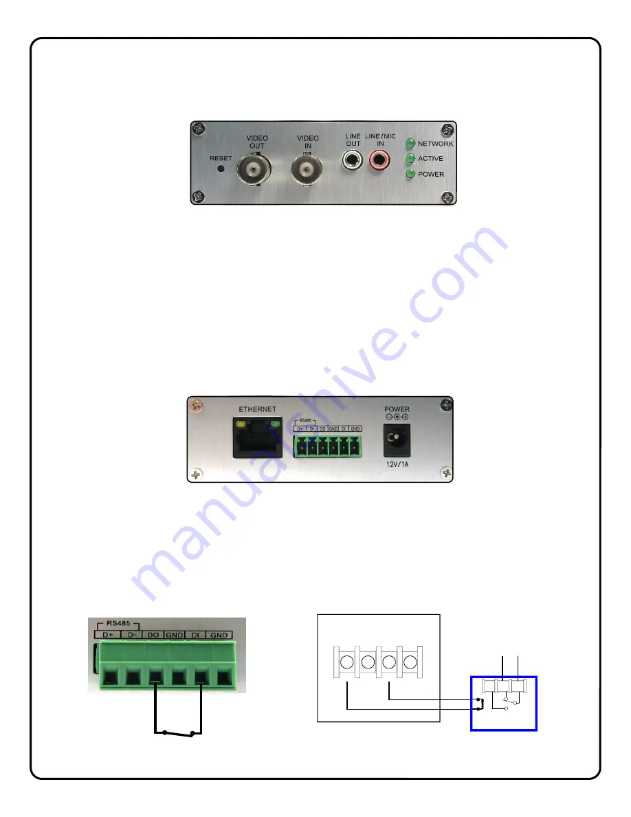
Descriptions of Terminals and Connections and Indicators 


VIDEO IN 

Connect BNC connector from the analog camera to the Video IN connector. 

VIDEO OUT

 (Optional)


To provide a video signal to local monitor or video distribution system, connect to video out terminal.  

Audio LINE / MIC IN 

 (Optional)


Connect a standard PC compatible microphone to the 3.5mm LINE/MIC Input for 2 way audio operation. 

Audio LINE OUT

 (Optional)


Connect a powered speaker to the 3.5mm LINE OUT jack for 2 way audio operation. 

NETWORK LED 

Flashes to indicate an active network connection. 

ACTIVE LED 

Flashes to indicate that video device is being accessed (viewed). 

POWER 

Lights to indicate that module power is present. 


ETHERNET 

Connect CAT5 cable from broadband modem or network to RJ-45 terminal. 

POWER 

Connect to supplied 12VDC power adapter. 


TRIGGER INPUT TERMINALS 

To initiate transmission of video to the VideoAlert.net server, wire a normally closed relay across the DO and DI terminals. 
A momentary open across this connection will trigger video. The trigger input feature must be activated in Advanced Fea-
tures (page 14). 

RED 

CONTROL 

PANEL 

AUX  

PWR 

12V 

(-) 

(-) 

(-) 

(+) 


PGM 

BLACK 


N/O N/C 

RB1000 

COM 

Typical connection to control panel PGM Output 
using NAPCO RB1000 form “C” relay  

DO  DI 

Note:

 Prior to using the audio 

feature, it is recommended that 
the viewer/listener obtain any 
required advance consent of the 
occupants of the premises.  

Содержание iSeeVideo ISEE-SCHGW

Страница 1: ...New York 11701 For Sales and Repairs 800 645 9445 For Technical Service 800 645 9440 Publicly traded on NASDAQ Symbol NSSC NAPCO 2009 Designed exclusively for use with NAPCO iSeeVideo VideoAlert net...

Страница 2: ...rt net service SCHGW EOP 12 Additional Gateway Kit Includes 1 ISEE SCHGW Power Adapter 1 ISEE EOP MOD200 6 CAT5 cable 12 months VideoAlert net service ISEE SCHGW 12 Single Channel Gateway Includes 1 I...

Страница 3: ...The modules create a powerline network ideal for the transmission of video signals at up to 200 megabits per second The EOP modules are fully capable of transmitting data across the phases of typical...

Страница 4: ...on page 6 3 Activate the new ISEE SCHGW account on the VideoAlert server page 7 4 Configure the gateway for motion detection triggering Optional Page 12 Optional The gateway may be configured for moti...

Страница 5: ...indicate that video device is being accessed viewed POWER Lights to indicate that module power is present ETHERNET Connect CAT5 cable from broadband modem or network to RJ 45 terminal POWER Connect t...

Страница 6: ...ntify the type of ISP or identify the modem or routers that may be in front of the internet connection provided by the subscriber In these cases wire as shown below 1 Connect the VIP devices directly...

Страница 7: ...s gateway and enter the Subscriber details see below ADD or REPLACE a VIP Device To add or replace a gateway to the account click here See Adding additional gateways to an existing account for more de...

Страница 8: ...firmation section verifies all information en tered above Be sure to check the accuracy of the information dis played and if changes are required click the Prev but ton to edit any previously entered...

Страница 9: ...iewer should always be enabled Click Update to add the new user and return to the previous screen or click Prev to cancel and return to the previous screen The system supports a maximum of 5 Users inc...

Страница 10: ...added S C _ _ _ _ _ _ Click Next 2 The Dealer Branding screen will appear Enter your Company Dealer Admin ID and Password and click Next 3 After Dealer Branding is complete click Add or Replace a VIP...

Страница 11: ...continue 5 The following screen allows the entry of the gateway description in the Enter New Device Description field Click the pull down menu and select Add De vice to complete the addition of the n...

Страница 12: ...en activated the ISEE SCHGW may be configured The next several pages will guide you through the on line configuration process Note If the ISEE SCHGW is only to be used for live viewing and there are n...

Страница 13: ...deo captured before the actual sensing of motion and the Post Capture Length being the length of the video after the sensing of motion Use the slider control for each respective Area box to adjust the...

Страница 14: ...nal Note Prior to using the audio feature it is recom mended that the viewer listener obtain any required advance consent of the occupants of the premises HW Trigger Input Select to enable the normall...

Страница 15: ...data and restore settings to the factory default values LED COLOR STATE STATUS Power Off No power Blue On Normal operation PLC link Blue On EOP network active at least one other device detected Blue...

Страница 16: ...3 seconds EOP Power LED flashes 2 Hold down the SECURITY button on other EOP module for 3 seconds EOP Power LED flashes 3 After a few seconds the Power and PLC link LED s should be on The configuratio...

Страница 17: ...pening of a protected door disarming of the system etc 6 I have a wireless router connected to my broadband modem How can I keep my network settings after the G BOX is installed Upon installation the...

Страница 18: ...self by a unique ID to the server to update the IP address Static IP Address An IP address whose value does not change DHCP Dynamic Host Configuration Protocol a protocol for assigning dynamic IP addr...

Страница 19: ...19 NOTES...

Страница 20: ...purporting to act on its behalf to modify to change or to assume for it any other warranty or liability concerning its products In no event shall NAPCO be liable for an amount in excess of NAPCO s or...

Отзывы: