10
CONTROL PANEL FIRMWARE
IMPORTANT:
Before upgrading firmware, the control
panel program must be uploaded to be re-downloaded when
the upgrade is complete.
The alarm control panel must have the correct firmware ver-
sion installed to use all features of the IBR-ZREMOTE and
the new iBridge Messenger service:
PCD-Windows Quickloader:
V6.12 or greater
(located on the enclosed IBR-ZREMOTE support CD)
Control panels GEM-X255, P9600 and P3200
require
firmware version
V60A23
or greater (included in IBR-
ZREMOTE box)
Control panels GEM-1664, P1632 and P816
require
firmware version
V31A
or greater (included in IBR-
ZREMOTE box)
New "
NO EPROM
"
GEM-P3200
,
P9600
or
X255
control
panels require firmware version
V71K
or greater (CD in-
cluded in the IBR-ZREMOTE BOX)
Note:
The following version control panels may be
upgraded for iBridge compatibility:
GEM-P3200 and P9600 controls running firmware ver-
sion 20 or greater, released in May of 1999
All GEM-X255 control panels
Any new GEM-P3200, GEM-P9600 or GEM-X255 control
panel running V70 or greater firmware does
not
require
an EPROM upgrade, it is iBridge compatible out of the
box.
GEM-P816 and GEM-P1632 control panels running firm-
ware version 10D or greater, released in November of
2005. The PC board revision number can be identified
by the revision number inside the triangular shaped stick-
er affixed to the PCB (requires 32 pin EPROM socket in
the control panel)
All GEM-P1664 control panels
UPGRADING THE EPROM CHIP
A.
If installing the IBR-ZREMOTE on a previously pro-
grammed control panel, launch Quickloader V6.12 (or
greater) and upload the control panel program configura-
tion to an account on your PC. In all cases ensure a con-
ventional keypad is connected at keypad address 1 for
steps that follow.
B.
Remove power from the control panel, disconnect the
battery wires and replace the EPROM with the new ver-
sion.
C.
Power the control panel, reconnect the battery wires, en-
ter Direct Address Program Mode and Cold Start the
panel:
To cold start the GEM-P186, GEM-P1632 or GEM-
P1664 Control Panels:
1. Enter Dealer Program Mode from keypad #1 (the de-
fault Dealer Code is 4 5 6 7 8 9).
2. Once in Dealer Program Mode, press
Reset
.
3. In Direct Address Programming Mode, enter the fol-
lowing address:
Panel firmware V11 and lower, enter address
1198
;
firmware V30 and higher, enter address
2286
4. Press the
ON / OFF
button to save.
PROGRAMMING WHEN USED WITH THE IBR-ZREMOTE
5. Press
Reset
twice to exit Dealer Program Mode. Veri-
fy the keypad display reads:
E09-00 Cold Start
.
To cold start the GEM-P3200, GEM-P9600 or GEM-
X255 Control Panels:
1. Enter Dealer Program Mode from keypad #1 (the Mas-
ter Security Code is printed on the silver shield inside
the control panel housing). Once in Dealer Program
Mode, press
Reset
.
2. In Direct Address Programming Mode, enter address
4093.
3. Press the
ON / OFF
button to save.
4. Press
Reset
twice to exit Dealer Program Mode. Veri-
fy the keypad display reads:
E09-00 Cold Start
.
D.
Download the saved control panel program configuration
back into the control panel or create and download new
control panel programming.
PROGRAMMING THE IBR-ZREMOTE IN
QUICKLOADER V6.12 (or greater)
In Quickloader V6.12 (or greater), in
Keypad Assignment
,
select the keypad address you will set up in step 5 for the
IBR-ZREMOTE, and change the keypad address
Type
to
"
RCM
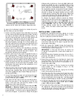
" and add the keypad into the Area (see image
at right), select
EZ Arm
(6 columns to the right on the
same screen). In the
Keypad Features
tab, check
"
Disable Code-Required-for-FM-Level 1
" (GEM-
P3200 / P9600 / X255 panels only).
PROGRAMMING THE TOUCHSCREEN
"KEYPAD ADDRESS" AND "KEYPAD TYPE"
Each IBR-TOUCH touchscreen must have its own unique
Keypad Address
; in addition, the
Keypad Type
must be de-
fined. Before proceeding, the
Setup Wizard
must be per-
formed. The
Setup Wizard
begins automatically when the
touchscreen is first started, but can also be manually started
in both the
Dealer Settings Menu
(see page 5) and the
User
Settings Menu
(see page 8).
For
Setup Wizard
step-by-step instructions for connect-
ing the touchscreen to an existing Wi-Fi Network
(networks without an ISEE-WAP), see the
NAPCO
iBridge™ IBR-TOUCH & IBR-TOUCH-WL Quick Start
Guide
(WI2297) available at
http://
tech.napcosecurity.com/
.
To connect the touchscreen to an existing Wi-Fi Network
(networks with an ISEE-WAP), see the
iBridge® Suite
Quick Start
(WI1980) available at
http://
tech.napcosecurity.com/
.
The
Keypad Type
is factory set as a GEM-RP1CAe2
"Classic" style keypad and is set to
Keypad Address
#1.
These factory settings can be changed if required. To
change the
Keypad Type
and
Keypad Address
, the
touchscreen must be powered on; the IBR-TOUCH must be
wired to the control panel keypad bus, and the IBR-TOUCH-
WL must have a local wireless connection to the "local"
StarLink Connect radio or the IBR-ZREMOTE Controller that
is physically located "locally", i.e. inside the premises and
connected to the control panel.


