background image

33

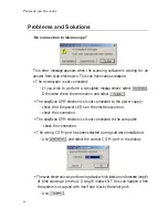
• If each image looks different:

• If the scan lines in ‘LineView’ are unstable and the image in the ‘TopView’

is not ‘sharp’:

The graphite surface

In a good top view image of graphite you will see a pattern consisting of
white, grey and black spots. It looks like a three dimensional image of balls
lying next to each other, but be careful: these are not the single atoms!
To interpret the image correctly you must first be aware that bright spots
show high points and dark spots low ones (except in ‘LineMath’ ‘Derive’).
In the lattice model of graphite one can see that there are two different
positions of the carbon atoms in the graphite crystal lattice: One with a
neighbouring atom in the plane below (grey) and one without a neighbour
in the lattice below (white). As a consequence, the electrical conductivity of
the graphite surface varies locally slightly so that the atoms without neigh-
bours appear higher than the others.

F

IRST

 M

EASUREMENTS

T

HE


GRAPHITE


SURFACE

Содержание easyScan E-STM

Страница 1: ...1 Operating Instructions easyScan E STM Version 2 1...

Страница 2: ...2 NANOSURF AND THE NANOSURF LOGO ARE TRADEMARKS OF NANOSURF AG REGISTERED AND OR OTHERWISE PROTECTED IN VARIOUS COUNTRIES JANUARY 2004 BY NANOSURF AG SWITZERLAND PROD BT00655 V2 1R1...

Страница 3: ...ling the sample 19 First Measurements 20 Starting the microscope 20 Approaching the tip 21 1 Coarse approach by hand 21 2 Fine approach by piezo motor 22 3 Automatic approach 23 Start measurement 24 A...

Страница 4: ...opy is one of the most exciting scientific techniques The insight into small dimensions has led to a new understanding of the structure of materials and forms of life With the help of the scanning tun...

Страница 5: ...ring that the size of the atom in relation to the tip is that of a golf ball to a mountain Scanning with the E STM In the E STM a platinum iridium tip is moved in three dimensions using piezo crystal...

Страница 6: ...sible to measure the tip sample movement very precisely One of the three piezo crystals the z piezo can now be used in a feedback loop that keeps the tunneling cur rent constant by appropriately chang...

Страница 7: ...use the tip would otherwise crash in to the sample What is so special about the Nanosurf easyScan E STM The E STM was designed to allow people without training as a physicist to do experiments in the...

Страница 8: ...se free Never touch either the wire for tips figure components 8 e the sample 8 g nor the open part of the STM scan head 2 with your fingers Only touch the sample holder 8 f at the black plastic end U...

Страница 9: ...aining the easyScan E Line software this manual software reference manual a test sheet and a sheet with the calibration information a Case for storing and transporting the instrument Additionally the...

Страница 10: ...he easyScan E SPM electronics 1 Make sure your computer is turned off Then connect the control elec tronics to a free serial port or RS232 or COM Port on your computer with the RS232 cable 4 If you ar...

Страница 11: ...Adapter ES option must be acquired to use the USB port Installation Procedure Turn on your computer and start Windows Do not run any other program while installing the scan software If you are using...

Страница 12: ...which the program files are to be copied Put them in the proposed directory unless the Program Files directory has a different name in your language of the Windows operating system Afterwards setup wi...

Страница 13: ...ion figure components 1 The setup program will start copying files onto your hard disk After successful installation you will get this confirmation Important The E Line software CD delivered with the...

Страница 14: ...he following dialog box appears By clicking Start Simulation a simulation of the microscope is started This imitates most of the functions of the real microscope The sample is replaced by a mathematic...

Страница 15: ...tting part of the wire cutters figure components 8 a the half round pliers 8 b and the pointed tweezers 8 c have been cleaned with ethanol Touch the Pt Ir wire 8 e with these tools only hold the end o...

Страница 16: ...n your scan head Single clamp see figure Mounting the tip under the single clamp a b 2 1 Mounting the tip under the single clamp 1 Put the tip wire on the tip holder parallel to the groove in the tip...

Страница 17: ...t clamp figure b 3 Push the wire in until it touches the second clamp 4 Lift the wire 5 Push the end of the wire below the second clamp 6 Lower the wire so that it lifts the second clamp figure c 7 Pu...

Страница 18: ...o the layered structure of graphite this can easily be done using a piece of adhesive tape see pictures below Put the sample on the table using the pair of tweezers Stick a piece of adhesive tape gent...

Страница 19: ...ng only its black plastic handle Put the prepared sample onto the magnetic end of the sample holder using a pair of tweezers See below Place the sample holder carefully in the scan head so that it doe...

Страница 20: ...This damages the end of the tip and it has to be cut again Starting the microscope The red LED of the E SPM electronics 1 should now be flashing when the easyScan E Line software has not been started...

Страница 21: ...the tip and the sample LED orange z piezo fully extended toward the sample the distance is too big not tunneling current can be detected LED red z piezo fully retracted The tip touched or crashed into...

Страница 22: ...mal drift in measurements at atomic scale 2 Fine approach by piezo motor Open the Panels menu in the easyScan E Line program window Select the Approach Panel Watch the distance between tip and sample...

Страница 23: ...using the up and down arrow keys on the keyboard The new value is automati cally used after one second The value of a numerical input can also be increased and decreased by clicking the arrow buttons...

Страница 24: ...unneling current defined by SetPoint is flowing between tip and sample LED green you can start measuring Click in the Scan Panel to maximize the range of the scan Start measuring by clicking in the Sc...

Страница 25: ...y the plane of the measurement and the sample s surface should lie in the x y plane of the scanner But mostly the sample plane is tilted with respect to that ideal plane In this case the sample cross...

Страница 26: ...he values of X Slope and Y Slope You can align the measurement plane with the sample plane using the fol lowing procedure Alter the value of X Slope using the arrow buttons until the x axis of the sca...

Страница 27: ...ignals amplified in order to observe the atomic struc ture Reminder Measurements on the nanometer scale are very sensitive Direct light fast movements causing air flow and temperature variations near...

Страница 28: ...zoom function by clicking with the right mouse button 3 Atomic arrangements can normally be made out at a ScanRange of about 4 nm and at a Z Range of about 1 5 nm Enter these values in Scan Panel one...

Страница 29: ...ine in the ScanPanel to 0 06s for atomic resolution View Panel If the contrast in the Top View window is too large or too small open the View Panel see figure and select in the Visible Input Range sec...

Страница 30: ...constant by the feedback loop and the movements of the tip by the z piezo are re corded This height profile is displayed in a LineView and the topo graphic image is displayed as a grey scale coded Top...

Страница 31: ...d A good tunneling contact is necessary for high quality images of atomic resolution If temperature variations are present they cause so called thermal drift Consequently the images are stretched This...

Страница 32: ...ems and solutions Image quality suddenly deteriorates In the following cases the tip has to be replaced i e cut freshly in order to establish a stable tunneling contact and high image quality If image...

Страница 33: ...the image correctly you must first be aware that bright spots show high points and dark spots low ones except in LineMath Derive In the lattice model of graphite one can see that there are two differe...

Страница 34: ...ve the higher than normal value of 0 25nm Measuring Gold It is more difficult to obtain good images of a gold Atomic structures are difficult to observe because the electrons on the surface are much m...

Страница 35: ...eptions to note select a gap voltage between 0 3 0 5V increase the value of parameter Time Line to 0 3s in the Scan Panel If you do not get stably reproduced scan lines you should look for another cle...

Страница 36: ...see also Software Reference Turning off and storing the instrument Exit the easyScan E Line program after having stored all desired images If you leave the program without saving some data the program...

Страница 37: ...still blue see chapter maintenance By storing the instrument in the suitcase it is protected from dust Simulta neously the rubber feet of the vibration isolation platform should be re lieved The dampi...

Страница 38: ...he sample holder must be stored in its container together with the moisture absorbing silica container The container is waterproof but not airtight The silica contains a blue indicator which turns pin...

Страница 39: ...der with a cotton swab if necessary lightly moistened with alcohol ensure the tip is removed when doing this Scan electronics Clean the cabinet and the controls with a soft cloth lightly moistened wit...

Страница 40: ...s is not connected to the power supply check that the power LEDs on the electronics are on check the connection The easyScan SPM electronics is not connected to the computer check the connection The w...

Страница 41: ...pen the Approach Panel s extended configuration using Increase the value of Stepsize and click Now the motor moves the sample holder with larger steps during automatic approach Save the new value for...

Страница 42: ...ts old value again Retract the sample using then perform a new approach If no improvement can be seen after going through these procedures you have to prepare a new tip Did the scan line in the LineVi...

Страница 43: ...suring graphite Z Offset does not change automatically In the default configuration of the easyScan E Line software the item in menu Options Auto Adjust Z Offset is activated If the numeric value of Z...

Страница 44: ...can range typ 0 5 m 1 m optional Maximum Z range 200 nm Drive resolution Z 0 003 nm Drive resolution XY 0 015 nm gap voltage 10V in 5mV steps Set point current 100nA in 25pA steps sample size max 10mm...

Страница 45: ...an Z Feedback Approach Spectroscopy RS232 Host PC RAM ROM 3 16 Bit DAC 10V 10V Optional 16Bit DAC Z Approach 3 16 Bit DAC 16 Bit DAC 12V Piezo Scanner X Y Z Axis 12 Bit DAC 12V Approach speed 16 Bit D...

Страница 46: ...46...

Страница 47: ...47...

Страница 48: ...48...

Отзывы: