N.KO UZ 15 Rapid Скачать руководство пользователя страница 42


42 


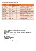
Link to video operation manual and etc: 
 

http://www.youtube.com/user/firmanko/videos?shelf_index=0&view=0&sort=dd


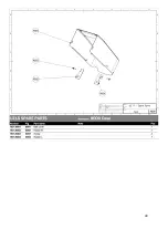
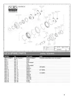
A copy of this manual is supplied with each machine UZ15 RAPID. 

All rights reserved.  

No  part  of  this  publication  may  be  reproduced  without  prior  consent  granted  by 
N.KO.  


Manufacturer's and Distributor's Address: 
 

N.KO spol. s r.o. 

a Member of Richtr Group 
Táborská 398/22 

293 01 Mladá Boleslav  

Czech Republic – Europe Union 
Phone: +420 326 772 001 fax: +420 326 774 279  

email:[email protected] 


Содержание UZ 15 Rapid

Страница 1: ...1 Bevelling Machine with Variable Angle and Automatic Feed NKO MACHINES UZ 15 Rapid Operating and Maintenance Instructions...

Страница 2: ...0 Working conditions 11 4 Installation Transport and lifting 11 Setting and connection 13 Checking before use 13 Dismantling and disposal 14 5 Usage Correct usage 14 Description of control devices 15...

Страница 3: ...rtant information for the operating personnel s safety Important Instruction which must be observed to ensure correct operation of the machine 1 2 Testing The bevelling machine is tested in our techni...

Страница 4: ...e at the Seller without undue delay after the Purchaser has found the defect at the latest by the end of the guarantee period however otherwise these claims expire To make a claim based on liability f...

Страница 5: ...5 1 5 Reference standards CE Declaration of Conformity...

Страница 6: ...se the machine for any purposes not indicated in this manual Never process products other than what is indicated here If you want to use the machine for purposes other than those defined ask the N KO...

Страница 7: ...ustment maintenance cleaning or repairs of the machine Attention Before starting work on the machine the operator must be acquainted with its properties and have read this entire manual Attention The...

Страница 8: ...during bevelling Attention The guard can only be removed if the machine is at standstill with the power supply plug disconnected Never use the machine without the safety guards in place The machine is...

Страница 9: ...s far from the cutting zone as possible Attention Always apply the safety regulations contained in this manual and ensure their observation and the elimination of all residual risks TECHNICAL SPECIFIC...

Страница 10: ...x 800 x 400 mm Weight 88 kg Exact voltage and frequency values are indicated on the motor identification label dle nastaven by adjustment 3 3 Noise level The machine has been designed and manufactured...

Страница 11: ...ith temperatures ranging between 10o C and 70o C All the other values remain unaltered INSTALLATION 4 1 Transport and lifting Important Activities described in this section must be performed by qualif...

Страница 12: ...ndition and suitable for the loads stated in paragraph 3 2 During handling of the machine wear protective clothing such as work gloves non slip shoes and helmet If the machine is in the transport pack...

Страница 13: ...he motor identification label Connect the electrical supply cable end to a plug according to your local power supply network Checking before use Important Never start the UZ 15 Rapid without carrying...

Страница 14: ...ed and sold for the purpose of bevelling the following kinds of metal parts and rolled metals iron steel up to R 60kg mm2 stainless steel brass copper and aluminium The maximum bevel dimensions and pr...

Страница 15: ...done on a stopped machine disconnected from the power supply Before starting work you must execute some settings according to the material thickness and bevel angle Setting the bevel angle The bevel a...

Страница 16: ...e it is very difficult to achieve these limits The condition for the attainment of these limit angles is the perfectly prepared the edges of the material However the edges before beveling usually does...

Страница 17: ...as to be still in contact with the body of bottom support Important The scale value position D Fig 5 3 2 corresponds to the difference between the bevel height dimension A in Fig 5 3 1 0 and the total...

Страница 18: ...loaded Note The data is valid only for strength of steel to 45 kg mm Fig 5 3 1 1 It is forbidden to set value C lower than indicated in the table the machine may become overloaded Material thickness u...

Страница 19: ...D Fig 5 3 2 that is 12 10 2 so the scale should read 2 mm Use the table to check whether the machine will not become overloaded The table indicates that the graded scale minimum value can be 1 5 mm Th...

Страница 20: ...llows Turn the hand wheel in the upper part of the work piece holder position E Fig 5 3 2 to adjust the holder cylinder height Adjust the cylinders so that they push on the work piece slightly and che...

Страница 21: ...previous paragraphs To ensure correct operation of the machine it is important to check whether the settings are correct None of the illustrated situations can occur the location of the work piece ma...

Страница 22: ...m right to left so that it can be caught by the cutting tool Protect the work piece coming out of the machine from falling by grasping it with both hands and pushing it to the rear part of the machine...

Страница 23: ...e machine and place it onto the left end of the work piece viewing from the front of the machine Fig 5 4 3 After completing the above operation the upper part of the work piece is bevelled If you need...

Страница 24: ...remove safety devices modify them or handle the safety equipment of the machine The manufacturer will reject any responsibility for machine safety in case of such activities Always use original spare...

Страница 25: ...he same oil or one of the oils recommended in paragraph 6 3 When changing the oil proceed as follows 1 Stop the machine and disconnect it from the power supply 2 Put the machine on its side and unscre...

Страница 26: ...A Fig 6 4 1 Loosen the main central roller and let the lower rest down to its lowest position Loosen the screw securing the tool position B Fig 6 4 1 and remove the tool from the shaft If the tool ca...

Страница 27: ...inue working with a blunt tool the blunt teeth may crack deep into the tool Then a tool damaged in this way must be ground until the cracked teeth disappear Thus you of course lose many precious meter...

Страница 28: ...spond to the bevel created ATTENTION The tool padding added to the current mill thickness must not exceed 29 mm In such case the machine will not work correctly and may be damaged ATTENTION Under the...

Страница 29: ...en operating the machine in areas with particularly dangerous influences AD or more you must take measures to increase the machine protection against electric shock Electrical energy the electrical po...

Страница 30: ...ial number required part description and its number quantity 8 2 Most wearing parts 1 cutting tool can be ground pos 2137 2 lower cylinders bearings pos 2020 3 work piece holder cylinders pos 3002 4 t...

Страница 31: ...31...

Страница 32: ...32...

Страница 33: ...33...

Страница 34: ...34...

Страница 35: ...35...

Страница 36: ...36...

Страница 37: ...37...

Страница 38: ...38...

Страница 39: ...39...

Страница 40: ...40...

Страница 41: ...41...

Страница 42: ...lied with each machine UZ15 RAPID All rights reserved No part of this publication may be reproduced without prior consent granted by N KO Manufacturer s and Distributor s Address N KO spol s r o a Mem...

Страница 43: ...Address BEVELER USA INC a Member of Richtr Group Business Office Workshop Warehouse 328 14th Street Ambridge PA 15003 Toll Free Number 1 800 973 1138 Phone Ambridge PA office 1 412 452 2563 email ser...

Отзывы: