10
20.0 Heat Exchangers
Multistack uses brazed plate stainless steel heat exchangers on the evaporator side of our modules. These heat exchangers are made of 316L stainless steel
and 99.9% pure copper. Condenser side heat exchangers are made from direct expansion copper tube and aluminum fin. Without proper water treatment
or due to abuse, the evaporator side heat exchangers can corrode and eventually develop an internal leak. In such an event it would become necessary to
replace the heat exchanger.
Following are the steps for field replacement of a failed evaporator side heat exchanger.
1. If the refrigerant has not been lost on the failed circuit, you should first do a standard refrigerant recovery.
2. Begin by isolating the module and draining the water/glycol from the loop.
3. Remove the 4- 8” round header pipes that attach to brazed plate heat exchanger (if you have a front module). For rear module(s), remove the crossover
pipes from the front module.
4. Cut the refrigerant lines below the elbows and sweat off remaining pipe.
5. Remove old heat exchanger and replace with new one.
6. Fit in copper connections and braze. Purge with Nitrogen while brazing.
7. After brazing, do a leak check and evacuate to a maximum of 500 microns. Charge the circuit according to the name plate specification.
If the brazed plate heat exchanger failure has caused water to enter into the refrigerant side, the compressor and condenser side heat exchanger should also
be checked for possible contamination. If water has entered into the compressor it is recommended the compressor be replaced as removing all the moisture
from the oil is very difficult. Replacement of the condenser side heat exchanger, the expansion valve, and installation of a liquid line filter drier with a water
core cartridge is also recommended. Evacuate the circuit to a maximum of 500 microns and let stand for 20 minutes. Charge the circuit, and run two-to-three
weeks with the high water core cartridge, and then replace with a standard core.
The condenser side heat exchangers on ASPX modules require periodic cleaning of the fins to keep airborne debris from plugging up the fins and causing high
pressure conditions. A coil cleaner suitable for copper and aluminum can be used for this.
21.0 Optional Low Ambient Package
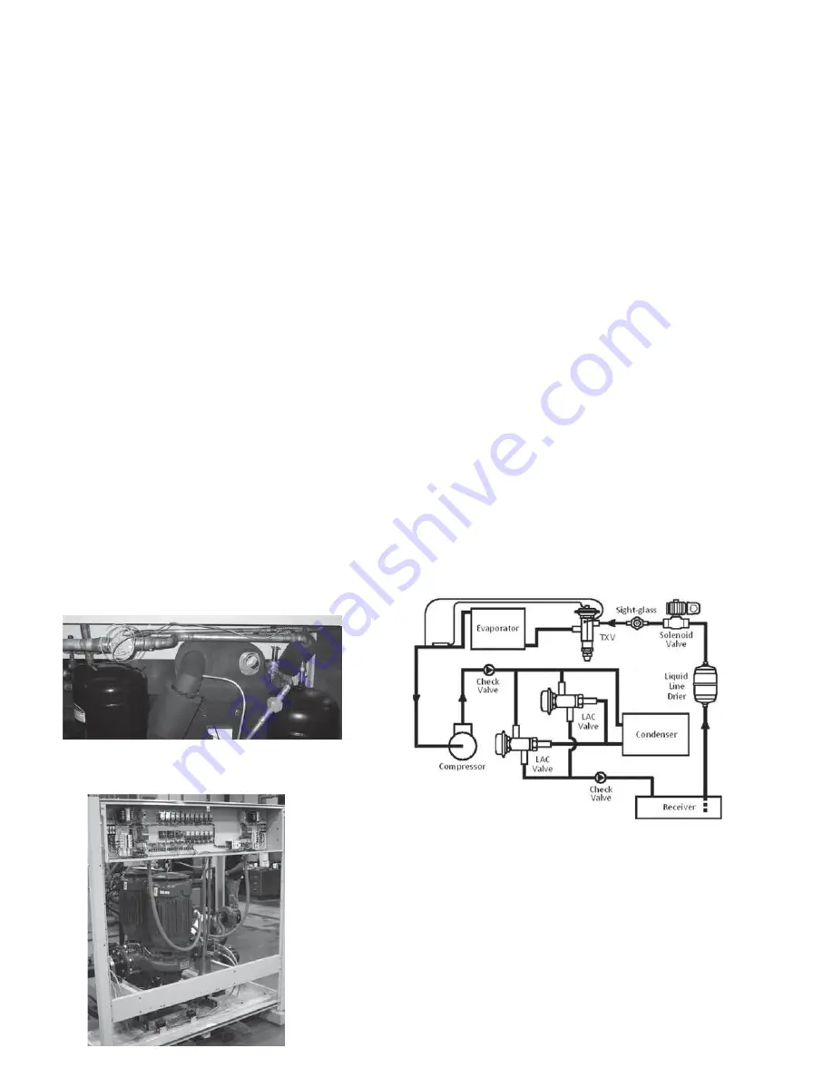
The standard operating range for ASPX modules is 95°F through 20°F. For operation from 20°F to negative 20°F modules should be ordered with the Low
Ambient Package. This includes the flooded head pressure control valve, properly sized liquid receiver tank to handle both summer and winter charge, liquid
line check valve, and setting the chiller into the Low Ambient or Low Temperature mode. Note on modules large than 15 tons, two head pressure control
valves will be used in parallel. When doing low ambient applications it is also suggested to use VFDs for condenser fan control.
22.0 Optional Pump Modules
To provide water flow to the chiller bank, Pump Modules can be provided in various sizes and
configurations to connect directly to the mechanical or free cooling modules. The standard pump
would be built in the same frame size as the cooling modules and come with a Series 4382 dual arm
with 1 primary pump and the 2nd as back up. Pumps can be manually rotated for equal run time or
special ordered with auto lead lag capability.


