


2.10
Initial Inspection
a)
Check to see that all moving parts are clean and free of any shipping debris
b)
Check to see that pump is securely bolted to mounting platform
c)
Check to see that driveline is securely fastened to the pump’s Gear Reducer input shaft with
adequate slip (1 inch minimum) in the slip joint
d)
Check the Fluid End bolts. Each has a mechanical indicator in the face and should be between
90 and 95 on the dial. Tighten as necessary, but do not surpass 95 on the dial. If the indicator is
not working return it to MSI for immediate replacement.
Note: In order to achieve the
necessary preload without damaging the bolt, DOW CORNING G-n Metal Assembly
Paste must be used.
e)
Make sure the Power Frame has correct oil in its reservoir (
)
f)
Make sure the plunger lube system has proper type of packing oil or grease
g)
Check to see that supercharge piping system is clean and all connections are tight
h)
Check to see that adequate water is available to suction manifold for testing
i)
Check to see that discharge piping connections are tight and all valves are open
j)
Start the supercharge pump and flush the air from the system
2.20
Seating Valves
If the pump was delivered with valves installed, then the valves were already seated during the FAT
test. If the valve seats were replaced in the field, the following procedure must be followed to set the
valve seats:
a)
The tapered valve seats must be fully seated to allow optimum flow area between the valve and
the seat. Washout may also occur between the valve and the fluid end if the valves are not fully
seated.
b)
Connect a 3/4” to 1” orifice test choke to the discharge circuit and adjust it to full open. Slowly
increase discharge pressure using the test choke until a series of audible popping noises are
heard. This indicates the seats have properly set in the taper. The approximate seating pressure
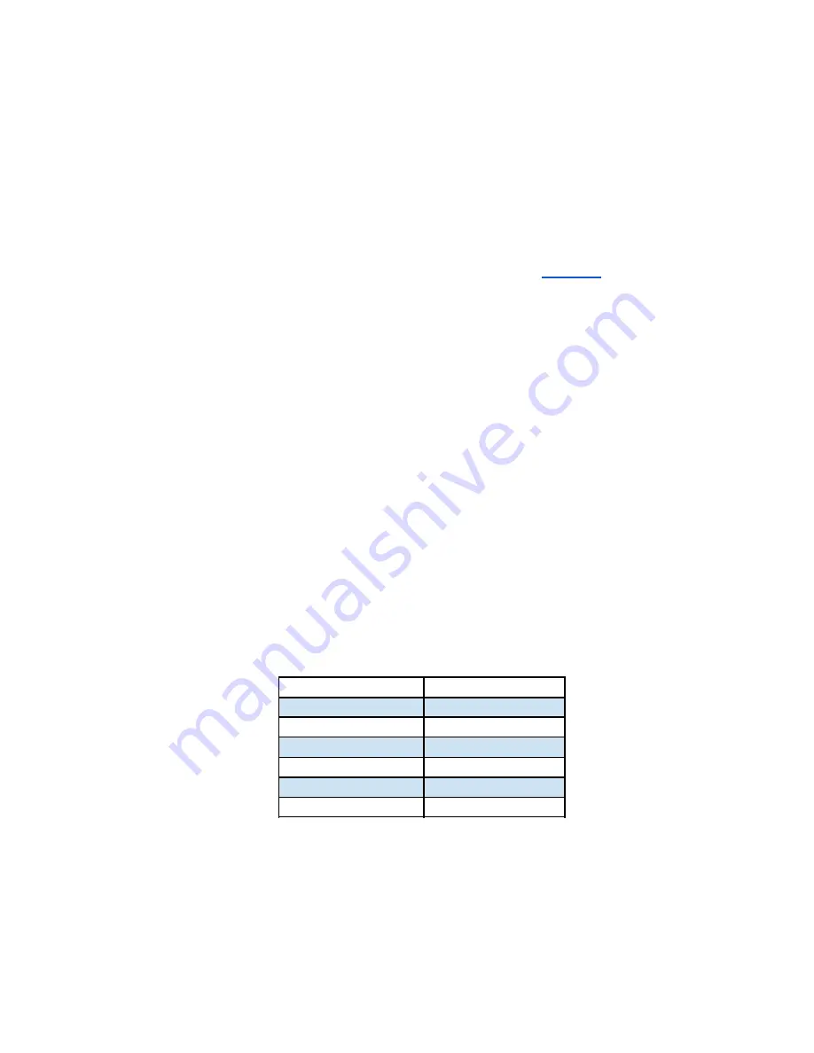
for each plunger size is as follows:
Plunger Diameter
Rated Pressure
2 ¾”
14,320 PSI
3”
12,030 PSI
3
¼
”
8,840 PSI
3 ½”
8,840 PSI
4”
6,765 PSI
4 ½”
5,345 PSI
c)
During this portion of the startup procedure, closely observe the plunger pump for any unusual
noise, vibration, fluid leaks and oil leaks. Record all pertinent information such as elapsed time,
ambient temperature, Power Frame lube oil temperature, and Power Frame lube oil pressure,
supercharge pressure, etc. After returning the engine to idle and transmission to neutral,
physically inspect the plunger pump before proceeding further.
Содержание QI-1000
Страница 7: ...1 20 Drawings Pump Assembly Overall Dimensions All Plunger Sizes TI 600 TRIPLEX...
Страница 8: ...QI 1000 QUINTUPLEX...
Страница 9: ...1 30 Dual Pump Assembly Overall Dimensions 1 30 1 600 HP Dual Pump Assembly Overall Dimensions...
Страница 10: ...1 30 2 1000 HP Dual Pump Assembly Overall Dimensions...
Страница 11: ...1 50 Drawings Gear Reducer Installation Positions 1 50 1 Gear Reducer Position Left Hand...
Страница 12: ...1 50 2 Gear Reducer Position Right Hand...
Страница 22: ...4 6 Lubrication Attachment Points See images below showing lubrication inlet and outlet locations...
Страница 36: ......
Страница 39: ...5 50 Power Frame Crank Rotation NOTE Crank Rotation can either be clockwise or counterclockwise...
Страница 43: ...Fluid End Assembly 3 25 4 50 continued...