Eco 40-55-75 manual revision 01/10
10
4.4 ASSEMBLY
Exhauster can be assembled either by the technicians authorised by the manufacturer or directly by the
customer, following these steps:
Unpacking.
Remove
all packing material from the machine, using suitable tools and setting it in a suitable place.
Dispose of the packing material according to the prevailing environment protection regulations.
(Visually)
check
machine external parts for damage, carefully ensure that there are no scratches, denting
or damaged parts.
Report
any fault, failure or missing parts found within five days from machine arrival. Beyond this term the
Manufacturer is no longer liable for the machine supplied.
WARNINGS AND PRECAUTIONS for installation
Always start by checking correct operation, assembly and efficiency of controls and safety systems.
In case
you find operating faults, immediately stop the machine and contact the AUTHORISED AFTER-SALES
SERVICE.
Pay attention
to the adhesive nameplates on the machine. Should they become damaged or
illegible, promptly change them. For this operation contact the AUTHORISED AFTER-SALES SERVICE or
the Manufacturer. Have
any maintenance intervention
-as per the definition of "user" given in the
foreword section- performed by qualified personnel.
Using spare parts
that do not comply with the
following specifications, any change or tampering (though small as they may be) relieve the Manufacturer
of any liability concerning the correct use, operation and safety of persons and/or property.
It is strictly
forbidden
to tamper with equipment, control organs and safety devices.
Dispose of waste
as required by
the prevailing laws.
If the machine is used by many operators
, all of them shall read the instructions for
use and indicate any maintenance intervention or parts replaced, or just suspected faults on the servicing
data sheet.
4.5 SET-UP
Set Exhauster and filtering unit on a flat and clean surface and ensure that the equipment and tools for
machine mechanical set-up are in place.
To handle the machine under safety conditions, lift it by means of a fork lift truck. After setting the machine
in position, level it and tighten the lock nuts to ensure it stays firmly in place.
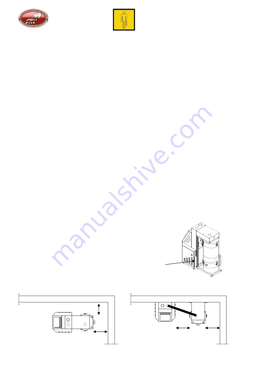
To divide the machine into two single parts, loosen the six screws (C) joining the filter to the machine.
The solenoid valve connection cable must be removed from the inside of the machine motor casing (about
4 meters). Stirrup the filter unit to the wall to assure its stability, by using the six holes used for mounting to
the machine.
N.B.: It shall always be possible to work all around the machine for maintenance purposes. Ensure
there is enough room in this area upon installation.
300 mm min.
300 mm min.
4m max.
300 mm min.
300 mm min.
“A”-type installation
“B”
-
type installation
C
Содержание CA Eco 40
Страница 22: ...Eco 40 55 75 manual revision 01 10 22 Electric circuit diagram Eco 40 ...
Страница 23: ...23 Eco 40 55 75 manual revision 01 10 Eco 40 ...
Страница 24: ...Eco 40 55 75 manual revision 01 10 24 Eco 55 75 ...
Страница 25: ...25 Eco 40 55 75 manual revision 01 10 Eco 55 75 ...
Страница 26: ...Eco 40 55 75 manual revision 01 10 26 Eco 55 75 Eco 40 ...
Страница 27: ...27 Eco 40 55 75 manual revision 01 10 ...
Страница 33: ...33 Eco 40 55 75 manual revision 01 10 Date Operation description Signature ...


